157
I
NSTALLING, POWERING, CONNECTING AND REGISTERING TERMINALS
CHAPTER 4 INSTALLATION
If an SB-8 / SB-8ANT is operated on two DSI interfaces, it is recommended always to use two neigh-
bouring ports.
Mitel Advanced Intelligent Network:
As the DECT systems of the individual nodes in an AIN do not run synchronously, the two DSI interfaces
of an SB-8 / SB-8ANT must always be connected to the same node.
For further display variants, see Operating state of the Mitel DECT radio units
.
Analogue phones Mitel 6710 Analogue, Mitel 6730 Analogue
The phones can be used as desktop model or as wall model.
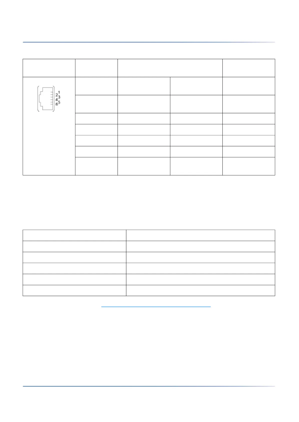
Table 4.45:Connections on the Mitel DECT radio units
RJ12 sockets Pin Socket 1: DSI interface Socket 2: Power
supply
SB-4+ SB-8 / SB-8ANT SB-4+ / SB-8 /
SB-8ANT
1 Local power supply
–
Local power supply
–
Local power supply
–
2 — b2 —
3 b1 b1 —
4 a1 a1 —
5 — a2 —
6 Local power supply
+
Local power supply
+
Local power supply
+
Table 4.46:Operating state display on Mitel DECT radio units
LED flashing (two LEDs on the SB-8) Information
green Operating state
red / green Startup procedure running
orange Transmission of DECT sequences
red Fault
not flashing and not lit LED switched off or radio unit defective or not in operation

 Loading...