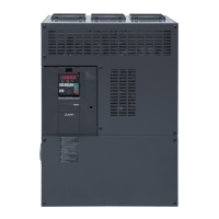
Inverter component names
INTRODUCTION
9
1
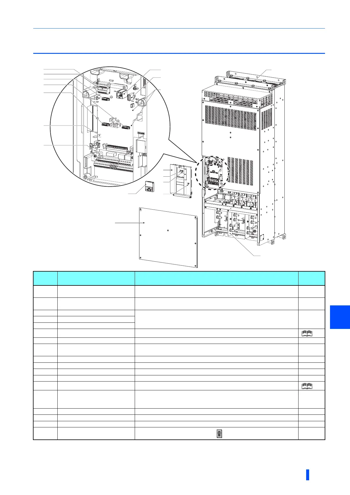
1.2 Inverter component names
Component names are shown below.
Refer to the FR-A800 Instruction Manual (Detailed).
The Vector control compatible options cannot be used with the slave.
Symbol Name Description
Refer to
page
(a) RS-485 terminals
Enables RS-485 communication between the master and the slave for the
parallel operation.
50
(b)
Terminating resistor selection
switch (SW1)
Select whether or not to use the terminating resistor for RS-485
communication.
50
(c) Plug-in option connector 1
Connects a plug-in option or a communication option.
Instruction
Manual of
the option
(d) Plug-in option connector 2
(e) Plug-in option connector 3
(f) Voltage/current input switch (SW2) Selects between voltage and current for the terminal 2 and 4 inputs.
(g) Control circuit terminal block Connects cables for the control circuit. 38
(h) PU connector
Connects the operation panel or the parameter unit. This connector also
enables the RS-485 communication.
52
(i) USB A connector Connects a USB memory device. 53
(j) Power lamp Stays ON while the power is supplied to the control circuit (R1/L11, S1/L21). 34
(k) Alarm lamp Turns ON when the protective function of the inverter is activated. 79
(l) Charge lamp Stays ON while the power is supplied to the main circuit. 34
(m) Operation panel (FR-DU08) Operates and monitors the inverter.
(n) Front cover (upper side)
Remove this cover for the installation of the product, installation of a plug-in
(communication) option, RS-485 terminal wiring, switching of the voltage/
current input switch, etc.
15
(o) Front cover (lower side) Remove this cover for wiring. 15
(p) Main circuit terminal block Connects cables for the main circuit. 33
(q) Cooling fan Cools the inverter. 92
(r)
Switches for manufacturer setting
(SW3 and SW4)
Do not change the initial setting (OFF ).
─
(h)
(g)
(f)
(p)
(j)
(l)
(a)
(e)
(c)
(d)
(m)
(k)
(n)
(o)
(i)
(q)
(r)
(b)
 Loading...