Communication connectors and terminals
50
INSTALLATION AND WIRING
2.7 Communication connectors and terminals
2.7.1 RS-485 terminal block
Connecting between the RS-485 terminals of the master/slave inverters enables communication for the parallel operation.
For wiring, refer to page 51.
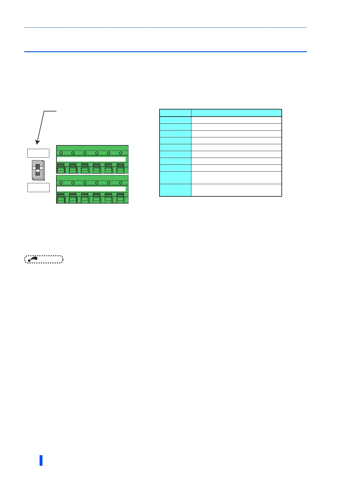
RS-485 terminal layout
Connection of RS-485 terminals and wires
• Use a 4-pair twisted cable for each connection.
• The size of RS-485 terminal block is the same as the control circuit terminal block. Refer to page 44 for the wiring method.
• The wiring length to the RS-485 terminals between the master/slave inverters should be within 5 m.
• To avoid malfunction, keep the RS-485 terminal wires away from the control circuit board.
• For wiring of the RS-485 terminals used with a plug-in option, lead the wires on the left side of the plug-in option.
Name Description
RXD1+ Inverter receive +
RXD1- Inverter receive -
RXD2+ Inverter receive + (for branch)
RXD2- Inverter receive - (for branch)
TXD1+ Inverter send +
TXD1- Inverter send -
TXD2+ Inverter send + (for branch)
TXD2- Inverter send - (for branch)
VCC
5V
Permissible load current 100 mA
GND
Earthing (grounding)
(connected to terminal SD)
Terminating resistor switch
Initially-set to "OPEN".
Set only the terminating resistor switch of
the remotest inverter to the "100Ω" position.
OPEN
100Ω
+-+
TXD RXD
-
VCC GND
+-+
TXD RXD
-
VCC GND
RXD1+ RXD1-
RXD2+ RXD2-
TXD1+ TXD1-
TXD2+ TXD2-
VCC GND
VCC GND
 Loading...