Main circuit terminals
INSTALLATION AND WIRING
35
2
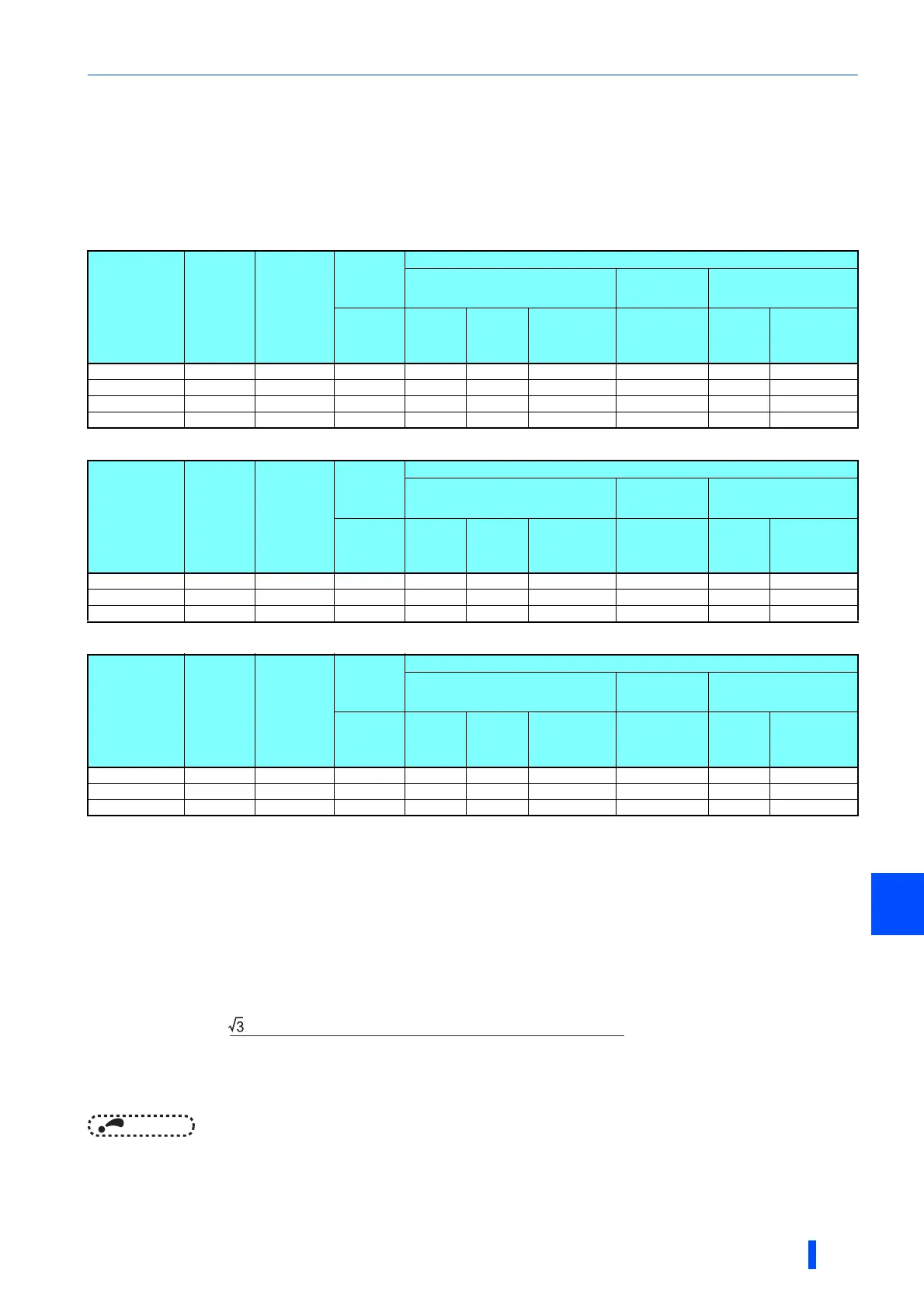
2.5.4 Applicable cables and wiring length
Select a recommended cable size to ensure that the voltage drop will be 2% or less.
If the wiring distance is long between the inverter and motor, the voltage drop in the main circuit will cause the motor torque to
decrease especially at a low speed.
The following tables for cable selection are one example in the case of a cable of 20 m long used at 440 V power supply.
• Single converter unit
• Single inverter (ND rating)
• Single inverter (LD rating)
The gauge of the cable with the continuous maximum permissible temperature of 90°C or higher. (LMFC (heat resistant flexible cross-linked
polyethylene insulated cable), etc.). It assumes a surrounding air temperature of 40°C or lower and in-enclosure wiring.
The recommended cable size is that of the cable (THHN cable) with continuous maximum permissible temperature of 90°C. It assumes a
surrounding air temperature of 40°C or lower and in-enclosure wiring.
(Selection example for use mainly in the United States.)
The cable size is that of the cable (XLPE cable) with continuous maximum permissible temperature of 90°C. It assumes a surrounding air
temperature of 40°C or lower and in-enclosure wiring.
(Selection example for use mainly in Europe.
The terminal screw size indicates the size of a terminal screw for R/L1, S/L2, T/L3, U, V, W, P/+, N/-, and a screw for earthing (grounding).
Screw size for earthing (grounding) is indicated in parentheses.
The line voltage drop can be calculated by the following formula:
Line voltage drop [V]=
Use a larger diameter cable when the wiring distance is long or when it is desired to decrease the voltage drop (torque
reduction) in the low speed range.
NOTE
• Tighten the terminal screw to the specified torque.
A screw that has been tightened too loosely can cause a short circuit or malfunction.
A screw that has been tightened too tightly can cause a short circuit or malfunction due to the unit breakage.
• Use crimp terminals with insulation sleeves to wire the power supply and motor.
Converter
model
FR-CC2-[ ]-P
Terminal
screw
Size
Tightening
Torque
N·m
Crimp
terminal
Cable gauge
HIV cables, etc. (mm
2
)
AWG/MCM
PVC cables, etc.
(mm
2
)
R/L1,
S/L2,
T/L3
R/L1,
S/L2,
T/L3
P/+, N/-
Earthing
(grounding)
cable
R/L1,
S/L2,
T/L3
R/L1,
S/L2,
T/L3
Earthing
(grounding)
cable
H400K M12 (M10) 46 C2-200 2200 2200 100 2400 2185 295
H450K M12 (M10) 46 C2-250 2250 2250 100 2500 2240 2120
H500K M12 (M10) 46 C2-200 3200 3200 2100 2500 2240 2120
H560K M12 (M10) 46 C2-200 3200 3200 2100 3350 3185 2150
Inverter
model
FR-A842-[ ]-P
Terminal
screw
size
Tightening
Torque
N·m
Crimp
terminal
Cable gauge
HIV cables, etc. (mm
2
)
AWG/MCM
PVC cables, etc.
(mm
2
)
U, V, W U, V, W P/+, N/-
Earthing
(grounding)
cable
U, V, W U, V, W
Earthing
(grounding)
cable
09620(400K) M12 (M10) 46 C2-200 2200 2200 100 2400 2185 295
10940(450K) M12 (M10) 46 C2-250 2250 2250 100 2500 2240 2120
12120(500K) M12 (M10) 46 C2-250 2250 3200 2100 2500 2240 2120
Inverter
model
FR-A842-[ ]-P
Terminal
screw
size
Tightening
Torque
N·m
Crimp
terminal
Cable gauge
HIV cables, etc. (mm
2
)
AWG/MCM
PVC cables, etc.
(mm
2
)
U, V, W U, V, W P/+, N/-
Earthing
(grounding)
cable
U, V, W U, V, W
Earthing
(grounding)
cable
09620(400K) M12 (M10) 46 C2-250 2250 2250 100 2500 2240 2120
10940(450K) M12 (M10) 46 C2-250 2250 3200 2100 2500 2240 2120
12120(500K) M12 (M10) 46 C2-200 3200 3200 2100 3350 3185 2150
× wire resistance[mΩ/m] × wiring distance[m] × current[A]
1000
 Loading...