APPENDIX
109
Appendix 2 Instructions for UL and cUL
(Standard to comply with: UL 508C, CSA C22.2 No.14)
General Precaution
CAUTION - Risk of Electric Shock -
The bus capacitor discharge time is 10 minutes. Before starting wiring or inspection, switch power off, wait for more than 10
minutes, and check for residual voltage between terminal P/+ and N/- with a meter etc., to avoid a hazard of electrical shock.
ATTENTION - Risque de choc électrique -
La durée de décharge du condensateur de bus est de 10 minutes. Avant de commencer le câblage ou l’inspection, mettez
l’appareil hors tension et attendez plus de 10 minutes.
Installation
The FR-A802 inverters with the below types of converter unit have been approved as products for use in enclosure.
Design the enclosure so that the surrounding air temperature, humidity and ambience of the inverter will satisfy the
specifications. (Refer to page 17.)
Wiring protection
For installation in the United States, Class T, Class J, Class CC, or Class L fuse must be provided, in accordance with the
National Electrical Code and any applicable local codes.
For installation in Canada, Class T, Class J, Class CC, or Class L fuse must be provided, in accordance with the Canadian
Electrical Code and any applicable local codes.
Maximum allowable rating by US National Electrical Code. Exact size must be chosen for each installation.
Wiring to the power supply and the motor
For wiring the input (R/L1, S/L2, T/L3) terminals of the converter unit and output (U, V, W) terminals of the inverter, use the UL
listed copper, stranded wires (rated at 75°C) and round crimping terminals. Crimp the crimping terminals with the crimping
tool recommended by the terminal manufacturer.
Short circuit ratings
Suitable For Use in A Circuit Capable of Delivering Not More Than 100 kA rms Symmetrical Amperes, 500 V Maximum.
Motor overload protection
When using the electronic thermal relay function as motor overload protection, set the rated motor current in Pr.9 Electronic
thermal O/L relay.
FR-CC2-[ ]-P H400K H450K H500K H560K
Rated fuse voltage (V) 500 V or more
Fuse maximum allowable rating (A)
1350 1500 1800 1800
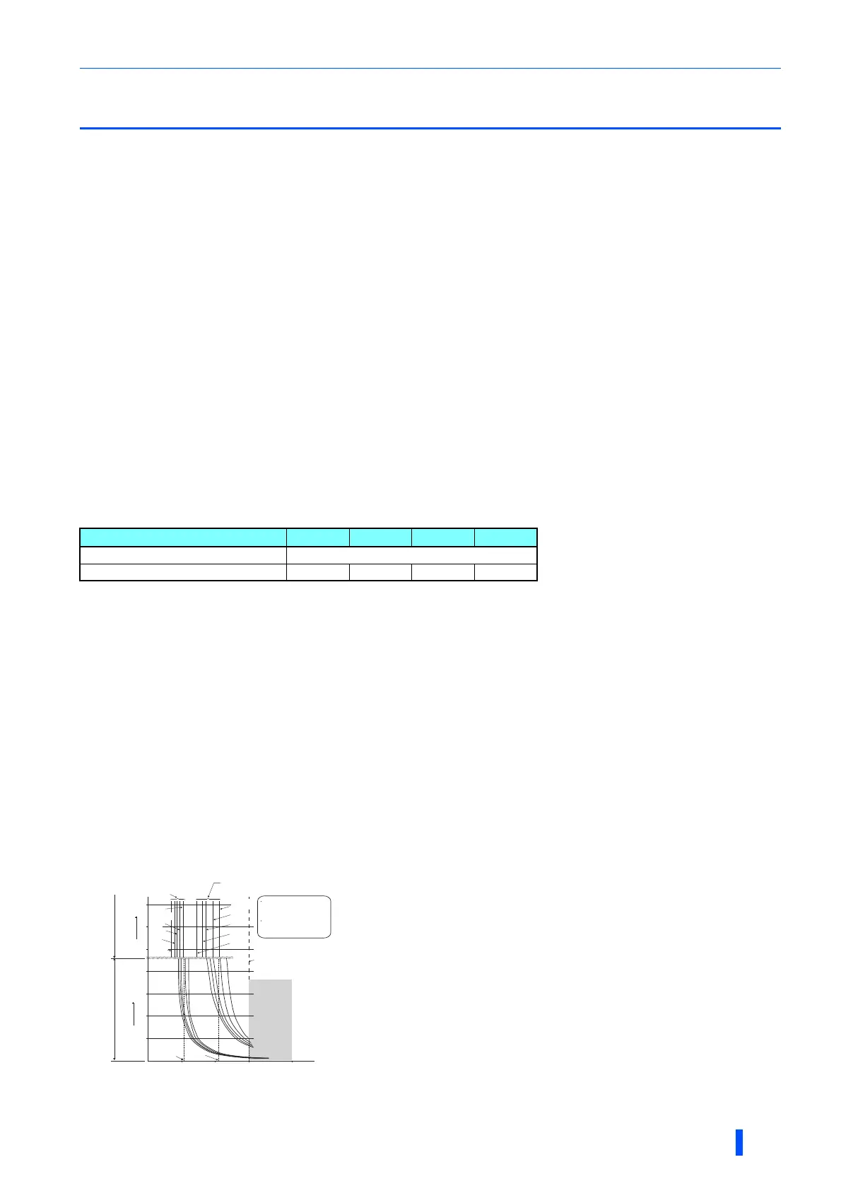
Operation characteristics of
electronic thermal relay function
This function detects the overload (overheat) of the motor and trips the
inverter by stopping the operation of the transistor at the inverter output side.
(The operation characteristic is shown on the left.)
• Mitsubishi constant-torque motor
(1) Set one of "1", "13" to "16" in Pr.71. (This setting will enable the 100%
constant-torque characteristic in the low-speed range.)
(2) Set the rated current of the motor in Pr.9.
When a value 50% of the inverter rated output current (current value) is set in Pr.9
The % value denotes the percentage to the rated inverter current. It is not the
percentage to the rated motor current.
When you set the electronic thermal relay function dedicated to the Mitsubishi
constant-torque motor, this characteristic curve applies to operation at 6 Hz or
higher.
Transistor protection is activated depending on the temperature of the heatsink.
The protection may be activated even with less than 150% depending on the
operating conditions.
230
52.5%
105%
50
100
150
60
120
180
240
50
60
70
Pr.9 = 50% setting
of inverter rating
∗1, 2
Pr.9 = 100% setting
of inverter rating
∗2
6 Hz
20 Hz
10 Hz
6 Hz
0.5 Hz
30 Hz
or more
∗3
30 Hz
or more
∗3
20 Hz
10 Hz
0.5 Hz
Range for
the transistor
protection
∗4
Second display in this range
Minute display in
this range
Operation time (min)Operation time (s)
Characteristic when
electronic thermal relay
function for motor
protection is turned off
(When
Pr.9
setting is 0(A))
Inverter output power (%)
(% to the inverter rated current)
Operation region
Region on the right of
characteristic curve
Non-operation region
Region on the left of
characteristic curve
 Loading...