Control circuit
INSTALLATION AND WIRING
47
2
2.6.6 When using separate power supplies for the
control circuit and the main circuit
Cable size for the control circuit power supply (terminals R1/L11 and S1/
L21)
• Terminal screw size: M4
• Cable gauge: 0.75 mm
2
to 2 mm
2
• Tightening torque: 1.5 N·m
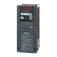
Connection method
When a fault occurs, opening of the electromagnetic contactor (MC) on the inverter power supply side results in power loss in
the control circuit, disabling the fault output signal retention. Terminals R1/L11 and S1/L21 are provided to hold a fault signal.
In this case, connect the power supply terminals R1/L11 and S1/L21 of the control circuit to the input side of the MC.
The terminals R1/L11 and S1/L21 are connected to the terminals P/+ and N/- with a jumper respectively. Do not connect the
power cable to incorrect terminals. Doing so may damage the inverter.
<Connection diagram>
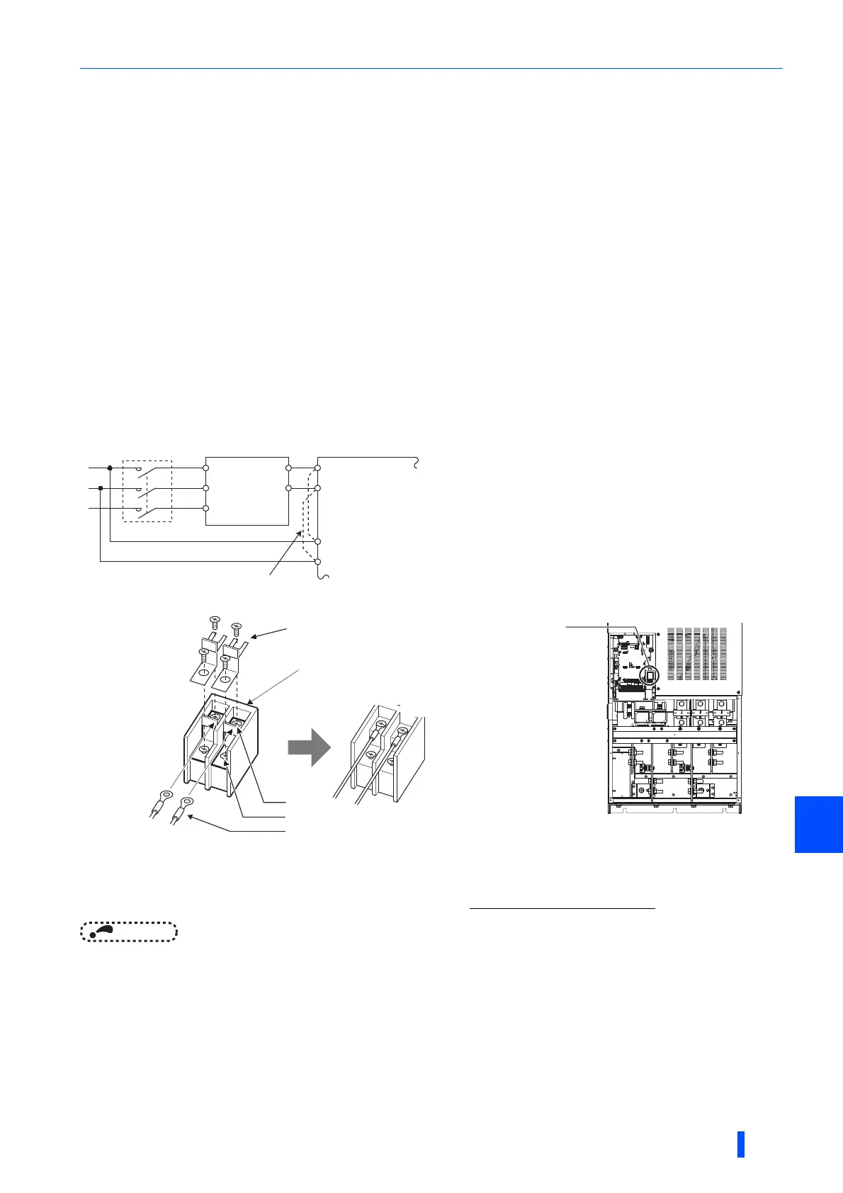
(a) Remove the upper screws.
(b) Remove the lower screws.
(c) Pull the jumper toward you to remove.
(d) Connect the separate power supply cable for the control circuit to the upper terminals (R1/L11, S1/L21)
.
NOTE
• When using separate power supplies, always remove the jumpers from terminals R1/L11 and S1/L21. The inverter may be
damaged if the jumpers are not removed.
• The voltage should be the same as that of the main control circuit when the control circuit power is supplied from other than
the input side of the MC.
• The power capacity necessary when separate power is supplied from R1/L11 and S1/L21 is 80 VA.
• If the main circuit power is switched OFF (for 0.1 s or more) then ON again, the inverter is reset and a fault output will not be
held.
InverterConverter unit
MC
R/L1
S/L2
P/+
N/-
T/L3
R1/L11
S1/L21
P/+
N/-
Remove the jumper
R1/L11
S1/L21
Power supply terminal block
for the control circuit
(c)
(d)
(a)
(b)
Power supply terminal block
for the control circuit
 Loading...