Main circuit terminals
INSTALLATION AND WIRING
33
2
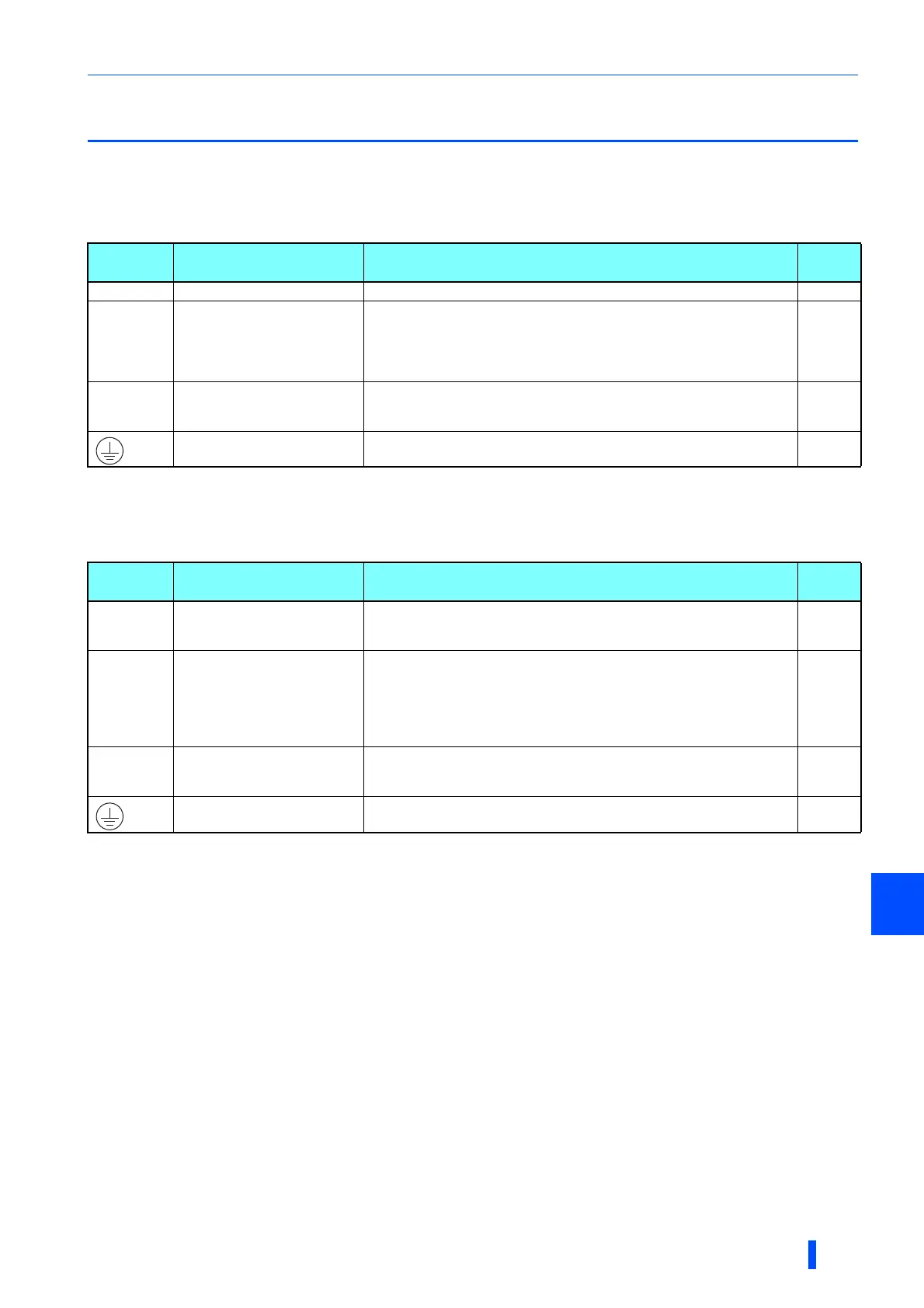
2.5 Main circuit terminals
2.5.1 Details on the main circuit terminals of the
inverter
2.5.2 Details on the main circuit terminals of the
converter unit
Terminal
symbol
Terminal name Terminal function description
Refer
to page
U, V, W Inverter output Connect these terminals to a three-phase squirrel cage motor. -
R1/L11,
S1/L21
Power supply for the control
circuit
Connected to terminals P/+ and N/-. To retain the fault display and fault
output, remove the jumpers across terminals R1/L11 and S1/L21, and apply
external power through these terminals.
The power capacity necessary when separate power is supplied from R1/L11
and S1/L21 is 80 VA.
47
P/+, N/- Converter unit connection
Install wiring in between the converter unit and between the inverter as
shown in the terminal connection diagram. (Wire one terminal P to another
terminal P, and do likewise for terminal N.)
29, 31
Earth (ground)
For earthing (grounding) the inverter chassis. This must be earthed
(grounded).
37
Terminal
symbol
Terminal name Terminal function description
Refer
to page
R/L1,
S/L2,
T/L3
AC power input Connect these terminals to the commercial power supply. -
R1/L11,
S1/L21
Power supply for the control
circuit
Connected to the AC power supply terminals R/L1 and S/L2. To retain the
fault display and fault output, remove the jumpers across terminals R/L1 and
R1/L11 and across S/L2 and S1/L21, and supply external power to these
terminals.
The power capacity necessary when separate power is supplied from R1/L11
and S1/L21 is 80 VA.
47
P/+, N/- Inverter connection
Install wiring in between the converter unit and between the inverter as
shown in the terminal connection diagram. (Wire one terminal P to another
terminal P, and do likewise for terminal N.)
29, 31
Earth (ground)
For earthing (grounding) the converter unit chassis. This must be earthed
(grounded).
37
 Loading...