31
OCH610G
31
9
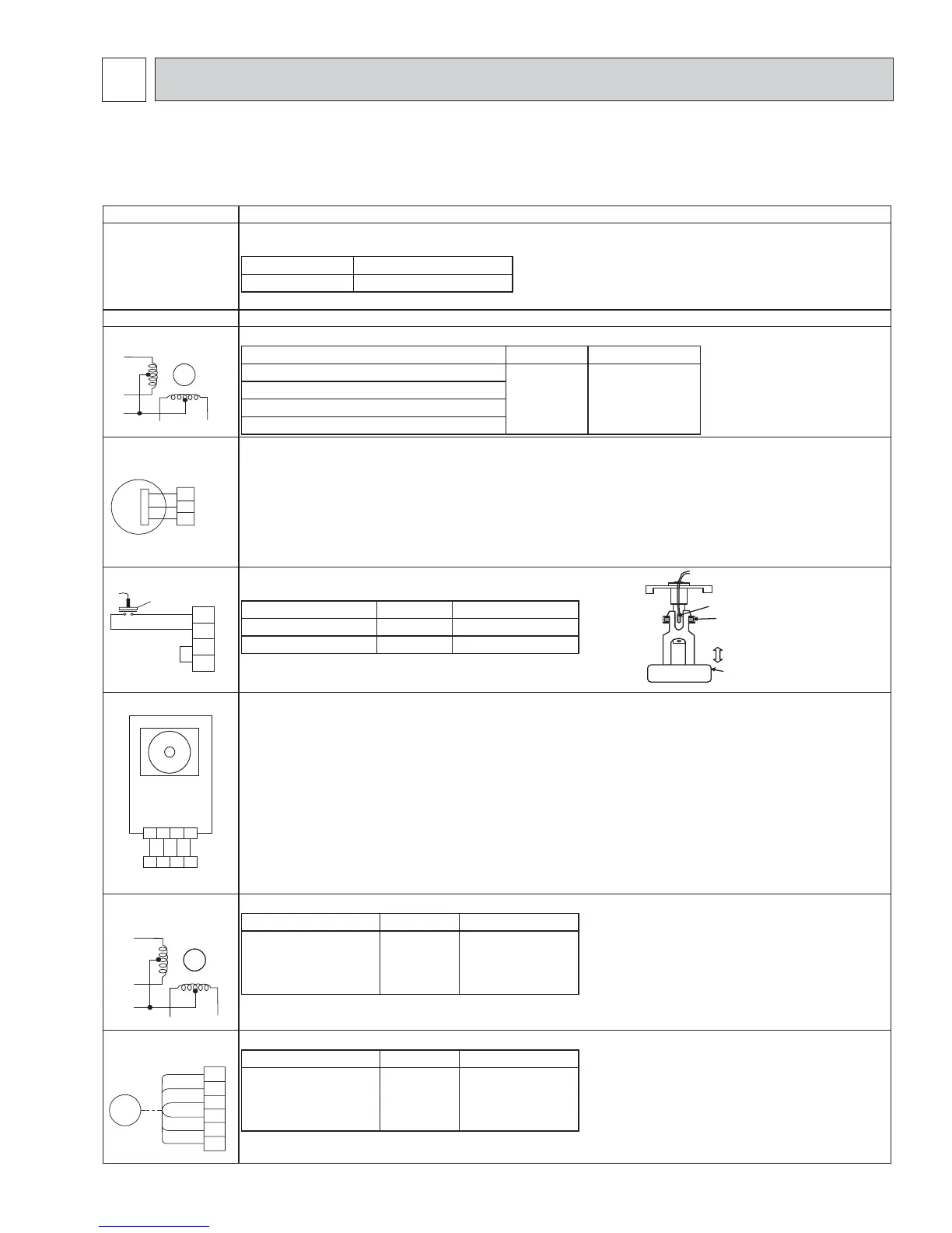
TROUBLESHOOTING
9-1. HOW TO CHECK THE PARTS
PLFY-EP06NEMU-E PLFY-EP08NEMU-E PLFY-EP12NEMU-E PLFY-EP15NEMU-E
PLFY-EP18NEMU-E PLFY-EP18NEMU-E1 PLFY-EP24NEMU-E PLFY-EP30NEMU-E
PLFY-EP36NEMU-E PLFY-EP48NEMU-E
Parts name Checkpoints
Room temperature
detection thermistor (TH21)
Pipe temperature detection
thermistor/liquid (TH22)
Pipe temperature detection
thermistor/gas (TH23)
Disconnect the connector then measure the resistance with a tester. (At the ambient temperature 50 to 86 °F)
Normal Abnormal
WR Open or short
Fan motor (MF) Refer to “9-1-3. DC Fan motor (fan motor/indoor controller board)”.
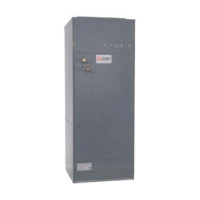
Vane motor (MV) Measure the resistance between the terminals with a tester. (At the ambient temperature of 68 to 86 °F)
Connector Normal Abnormal
Red–Yellow (
5
–
3
,
0
–
8
,
5
–
3
,
)
–
8
)
300
Open or short
Red–Blue (
5
–
1
,
0
–
6
,
5
–
1
,
)
–
6
)
Red–Orange (
5
–
4
,
0
–
9
,
5
–
4
,
)
–
9
)
Red–White (
5
–
2
,
0
–
7
,
5
–
2
,
)
–
7
)
Drain pump (DP)
1
&KHFNLIWKHGUDLQÀRDWVZLWFKZRUNVSURSHUO\
2
Check if the drain pump works and drains water properly in cooling operation.
3
,IQRZDWHUGUDLQVFRQ¿UPWKDWWKHFKHFNFRGHZLOOQRWEHGLVSOD\HGPLQXWHVDIWHUWKHRSHUDWLRQVWDUWV
Note: The drain pump for this model is driven by the internal DC motor, so it is not possible to
measure the resistance between the terminals.
Normal
5HG±%ODFN,QSXW9'&ĺ7KHSXPSPRWRUVWDUWVWRURWDWH
Purple–Black: Abnormal (check code 2502) if it outputs 0–13 V square wave (5 pulses/rotation), and the number of rotation is not normal.
'UDLQÀRDWVZLWFK)6 Measure the resistance between the terminals with a tester.
State of moving part Normal Abnormal
UP Short Other than short
DOWN Open Other than open
3D i-see Sensor Turn the power ON while the i-see Sensor connector is connected to the CN4Z on indoor controller board.
A communication between the indoor controller board and i-see Sensor board is made to detect the connection.
Normal: When the operation starts, the motor for i-see Sensor is driven to rotate the i-see Sensor.
Abnormal: The motor for i-see Sensor is not driven when the operation starts.
Note: The voltage between the terminals cannot be measured accurately since it is pulse output.
i-see Sensor motor (MT)
(Option)
Measure the resistance between the terminals with a tester. (At the ambient temperature of 68 to 86°F)
Connector Normal Abnormal
Red–Yellow
Red–Blue
Red–Orange
Red–White
250 Open or short
Linear expansion valve
(LEV)
Disconnect the connector then measure the resistance with a tester. (At the coil temperature 50 to 86 °F)
Connector Normal Abnormal
White–Red
Yellow–Brown
Orange–Red
Blue–Brown
200 ± 10% Open or short
MV
YE
BU
RD
OG
WH
RD
VT
BK
1
2
3
2
1
Moving part
4
3
Switch
Magnet
Moving
Part
4321
43 1
2
BK
BK
BK
BK
OG
RD
WH
BU
YE
M
LEV
BN
CN60
BU
1
2
3
4
5
6
OG
WH
RD
YE
Refer to “9-1-1. Thermistor”.
Refer to “9-1-2. Linear expansion valve”.
 Loading...