OPERATING PROCEDURE PHOTOS/FIGURES
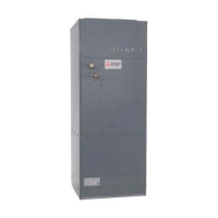
9. Removing the drain pan
(1) Remove the intake grille and the filter. (See Procedure 1.)
(2) Remove the electrical box cover. (See Procedure 2.)
(3) Disconnect the connectors. (Refer to Procedure 4.)
(4) Remove the grille. (See Procedure 8.)
(5) Remove the electrical box. (See Procedure 5.)
(6) Remove the 2 bell mouth fixing screws (tapping screw: 4
× 10) to remove the bell mouth. (See Photo 6.)
(7) Remove the 4 drain pan fixing screws (M5 × 10) and pull
out the drain pan.
Photo 13
Drain pan
fixing screw
Drain pan
fixing screw
Drain pan
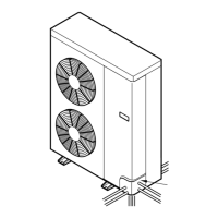
10. Removing the pipe temperature detection thermistor/liq-
uid (TH22) and pipe temperature detection thermistor/gas
(TH23)
(1) Remove the intake grille and the filter. (See Procedure 1.)
(2) Remove the electrical box cover. (See Procedure 2.)
(3) Disconnect the connectors. (Refer to Procedure 4.)
(4) Remove the grille. (See Procedure 8.)
(5) Remove the electrical box. (See Procedure 5.)
(6) Remove the 2 bell mouth fixing screws (tapping screw: 4
× 10) to remove the bell mouth. (See Photo 6.)
(7) Remove the drain pan. (See Procedure 9.)
(8) Remove the thermistors which are inserted into the hold-
ers installed to the thin copper pipe.
Photo 14
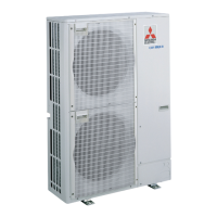
11. Removing the drain pump (DP) and float switch (FS)
(1) Remove the intake grille and the filter. (See Procedure 1.)
(2) Remove the electrical box cover. (See Procedure 2.)
(3) Disconnect the connectors. (Refer to Procedure 4.)
(4) Remove the grille. (See Procedure 8.)
(5) Remove the electrical box. (See Procedure 5.)
(6) Remove the 2 bell mouth fixing screws (tapping screw: 4
× 10) to remove the bell mouth. (See Photo 6.)
(7) Remove the drain pan. (See Procedure 9.)
Drain pump (DP)
(8) Cut the hose band and remove the hose. (See Photo
15.)
(9) Loosen the clamp for the drain pump. (See Photo 15.)
(10)
Remove the 2 drain pump base fixing screws (tapping
screw: 4 ×10), and loosen the 2 hooks to remove the
drain pump assembly.
Float switch (FS)
(8) Loosen the clamp for the drain pump. (See Photo 15.)
(9) Remove the float switch fixing screw (tapping screw: 4
×10), and loosen the hook to remove the float switch. (See
Photo 15,16.)
Photo 15
Float switch fixing
screws
Drain pump
base fixing
screws
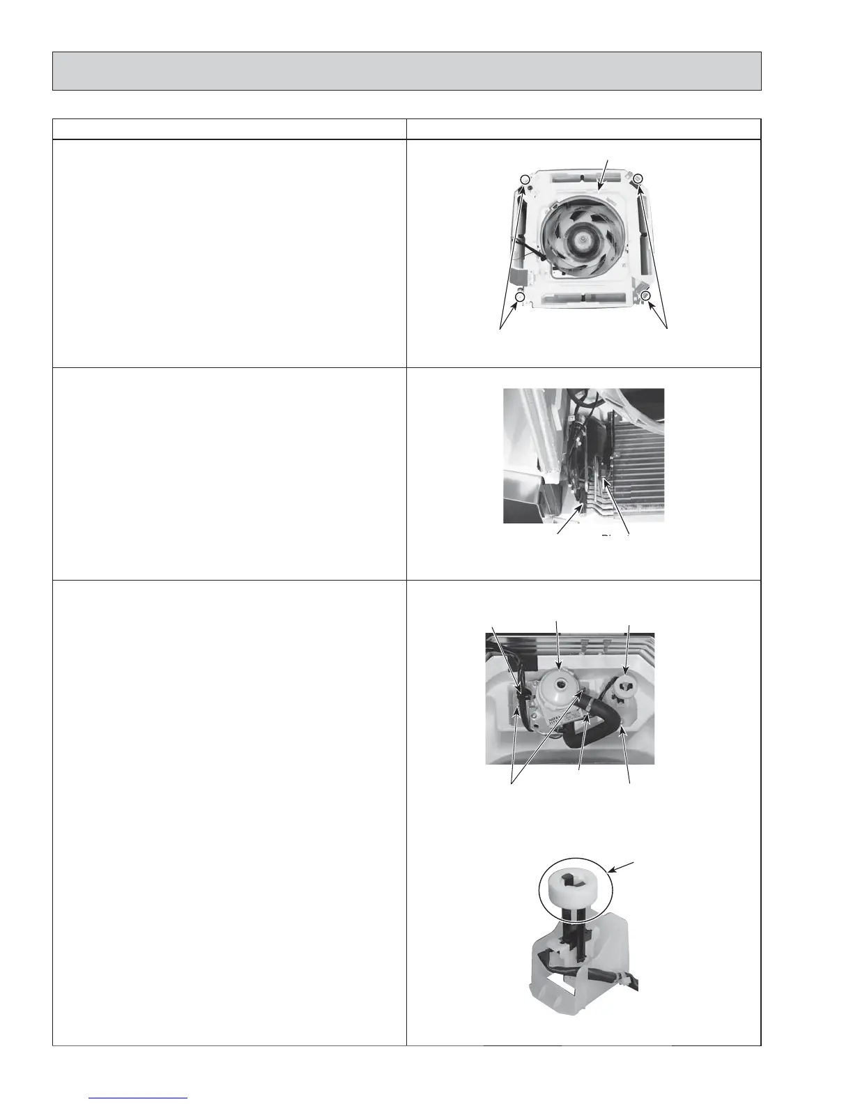
Photo 16
Pipe temperature
detection thermistor/
gas (TH23)
Pipe temperature
detection thermistor/
liquid (TH22)
'RQRWKROGWKLVÀRDWLQJ
part when lifting;
Doing so will cause
malfunction.
Drain pump
Hose band
Float switch
Clamp
Float switch
42
OCH610G
 Loading...