38
OCH610G
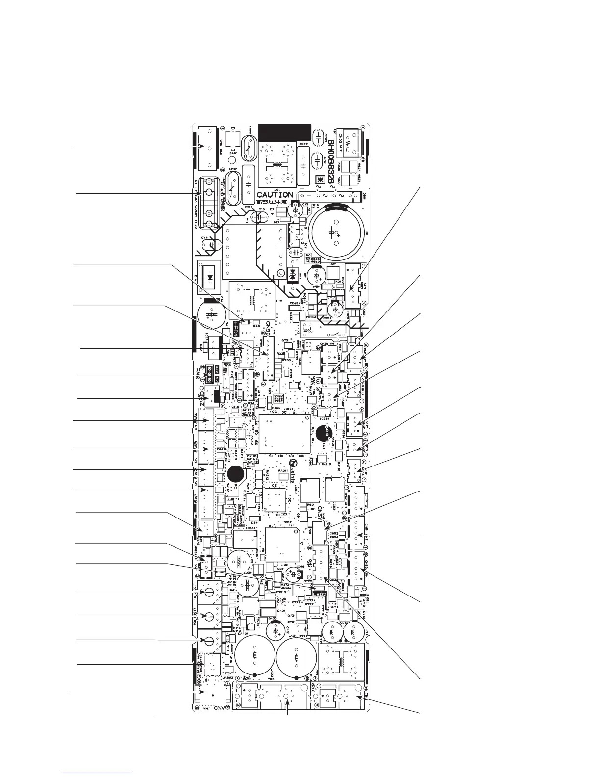
9-3. TEST POINT DIAGRAM
9-3-1. Indoor controller board
Note: The voltage range of 12 V DC in this page is between 11.5 to 13.7 V DC.
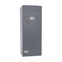
PLFY-EP06NEMU-E PLFY-EP08NEMU-E PLFY-EP12NEMU-E PLFY-EP15NEMU-E
PLFY-EP18NEMU-E PLFY-EP18NEMU-E1 PLFY-EP24NEMU-E PLFY-EP30NEMU-E
PLFY-EP36NEMU-E PLFY-EP48NEMU-E
CN44
Pipe temperature thermistor
1–2: Liquid (TH22)
3–4: Gas (TH23)
CN4F
Drain float switch (FS)
CN20
Room temperature
thermistor (TH21)
CN27
Damper signal output
12 V DC (1: +)
CN90
Connect to the wireless
remote controller board
(W.B)
CNP
Drain pump output (DP)
1–3: 12 V DC
FUSE
6.3 A, 250 V
CN24
External heater
12 V DC (1 : +)
CND
Power supply for indoor controller board
3–5: 208–230 V AC
SW22
Pair No. setting for wireless remote
controller
CNMF
Connect to the
fan motor (MF)
1–4: 310–340 V DC
5–4: 15 V DC
6–4: 0–6 V DC
7–4:
0 or 15 V DC (Stop)
7.5 V DC (Operation)
(12 V DC pulse)
LED1
Main power supply
(Indoor unit: 208–230 V)
CN51
Centrally control
1–2 : Control signal
12 V DC pulse input (1 : +)
3–4 : Operation indicator
12 V DC (3 : +)
3–5 : Malfunction indicator
12 V DC (3 : +)
CN52
Remote indicator
1–2
: Status lamp 12 V DC (1 : +)
Fan motor output (SW1-5 OFF)
Thermostat ON (SW1-5 ON)
1–3: Cooling/Dry status lamp
12 V DC (1 : +)
1–4: Heating status lamp
12 V DC (1 : +)
CN4Z
i-see Sensor (sensor)
CN60
Linear expansion valve (LEV) out-
put 12 V DC pulse output
CN5Y
i-see Sensor motor output (MT)
12 V DC pulse output
TB15
MA-Remote controller connecting wire
1–2: 8.7–13 V DC (non-polar)
CNV
Vane motor output
12 V DC pulse
CN32
Remote switch
LED2
Power supply for
MA-Remote controller
SW3
Function setting
SW4
Model selection
SW2
Capacity setting
SW1
Function setting
SWE
Test run (Drain pump and indoor fan motor )
CN105
IT Terminal
TB5
M-NET transmission connecting wire
24–30 V DC (non-polar)
SW14
Branch No.
SW21
Ceiling height and discharge outlet
number selector
SW11
Address setting 1s digit
SW12
Address setting 10s digit
 Loading...