66
6 INSTALLATION AND WIRING
6.4 Wiring
Precautions for wiring the safety remote I/O module to safety
devices
This section describes the precautions for the wiring. To wire the safety remote I/O module to each safety device according to
Category 4, perform both of the following for the safety remote I/O module.
• Double wiring inputs/outputs
• Executing the self-diagnostic function (dark test)
When performing the operations above, observe the precautions below.
When wiring the input part
■Combination of input terminals
The following table lists the applicable combinations of input terminals. If the combinations other than the below are used, a
minor error occurs.
• NZ2GFSS2-32D-S1
• NZ2GFSS2-8D-S1, NZ2GFSS2-16DTE-S1
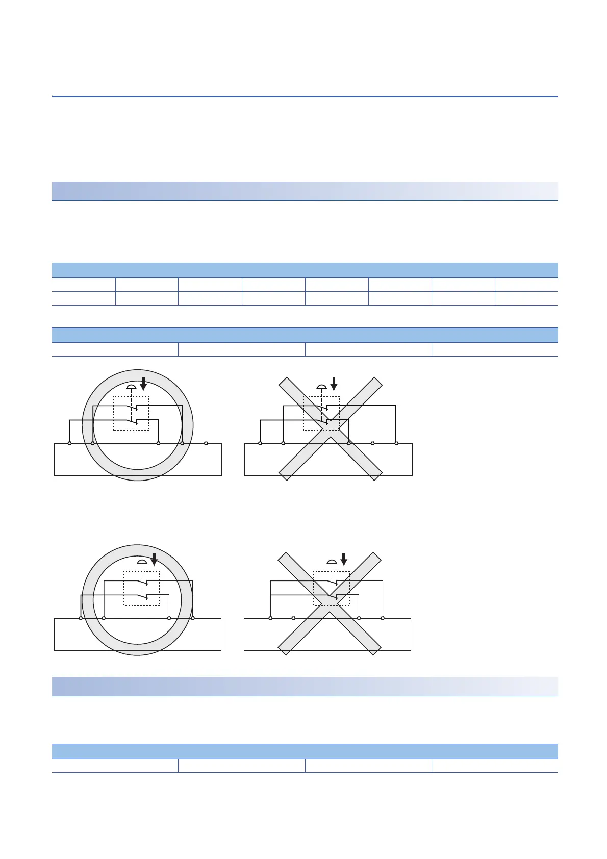
■Test pulse output terminal combination
The same test pulse cannot be used for the combinations for one device. If the combinations of the same test pulse are used
for one device (X0 and T0, X1 and T0 for instance), a minor error occurs.
When wiring the output part
■Combination of output terminals
The following table lists the applicable combinations of output terminals. If the combinations other than the below are used, a
minor error occurs.
Combination of input terminals
X0, X1 X2, X3 X4, X5 X6, X7 X8, X9 XA, XB XC, XD XE, XF
X10, X11 X12, X13 X14, X15 X16, X17 X18, X19 X1A, X1B X1C, X1D X1E, X1F
Combination of input terminals
X0, X1 X2, X3 X4, X5 X6, X7
Combination of output terminals
Y0, Y1 Y2, Y3 Y4, Y5 Y6, Y7
X2(-)X1(-)X0(-)T1(+)T0(+)X2(-)X1(-)X1(-)X1(-)X0(-)T1(+)T0(+)T0(+)T0(+)
Safety remote I/O moduleSafety remote I/O module
Safety remote I/O moduleSafety remote I/O module
Safety remote I/O module
Safety remote I/O module
X1(-)X0(-)T1(+)T1(+)T0(+)X1(-)X0(-)X0(-)T1(+)T0(+)T0(+) T1(+)X0(-)T0(+)
Safety remote I/O moduleSafety remote I/O module
Safety remote I/O moduleSafety remote I/O module
Safety remote I/O module
Safety remote I/O module
 Loading...