Installation
-
83
-
'13 • HM-T-193
Start-up and inspection
Commissioning
Outdoor unit
1. Check that the miniature circuit-breaker (FA2) in indoor
unit is on.
Indoor unit
1. Check that the temperature limiter (FD1) has not tripped.
2. S
witch on the main circuit breaker and check that the
miniaturecircuitbreaker(FA1,FA3)inindoorunitison.
3. Setswitch(SF1)to“1”(theswitchshouldbeswitchedon
for 6 hours before the compressor can be started).
When
switch (SF1) is set to “0” - wait at least 1 minute
before setting it back to “1”.
4. Se
lect operating mode “Add. heat only” by holding in the
operating mode button for 7 seconds.
5. Set the date and time in Menu 7.1 and 7.2.
6. Set the language in Menu 8.1.2.
7. Select “Service” in Menu 8.1.1.
8.
SetMenu9.3.14to“NoHW”whenHT30isconnected.
9. Select additional heat source type in Menu 9.2.8.
10.Setthefusesize
onknob(R24).CheckthevalueinMenu
8.3.1.
11.Setthe
maximmersionheateroutputonknob(R25).
CheckthevalueinMenu8.3.2.
12. Select the desired heating curve in Menu 2.1.2 and set the
parallel offset using the knob.
13.Checkthatthehot
watertemperatureinMenu1.0exceeds
25 °C.
14.When t
he above steps have been completed, select
operating mode “Auto”.
The he
at pump starts 30 minutesafter the outdoorunitis
powered if there is a heat demand.
Setting system flow heating
1. Ensure that the heat pump produces heating for the climate
system.
2. Select “On” in Menu 9.6.2.
3. Sel
ect thevalue inMenu9.6.1. according tothe table
below.
FDCW71 FDCW100 FDCW140
55 40 57
NOTE
If it is not shown, set the Menu 8.1.1 to “ Service”.
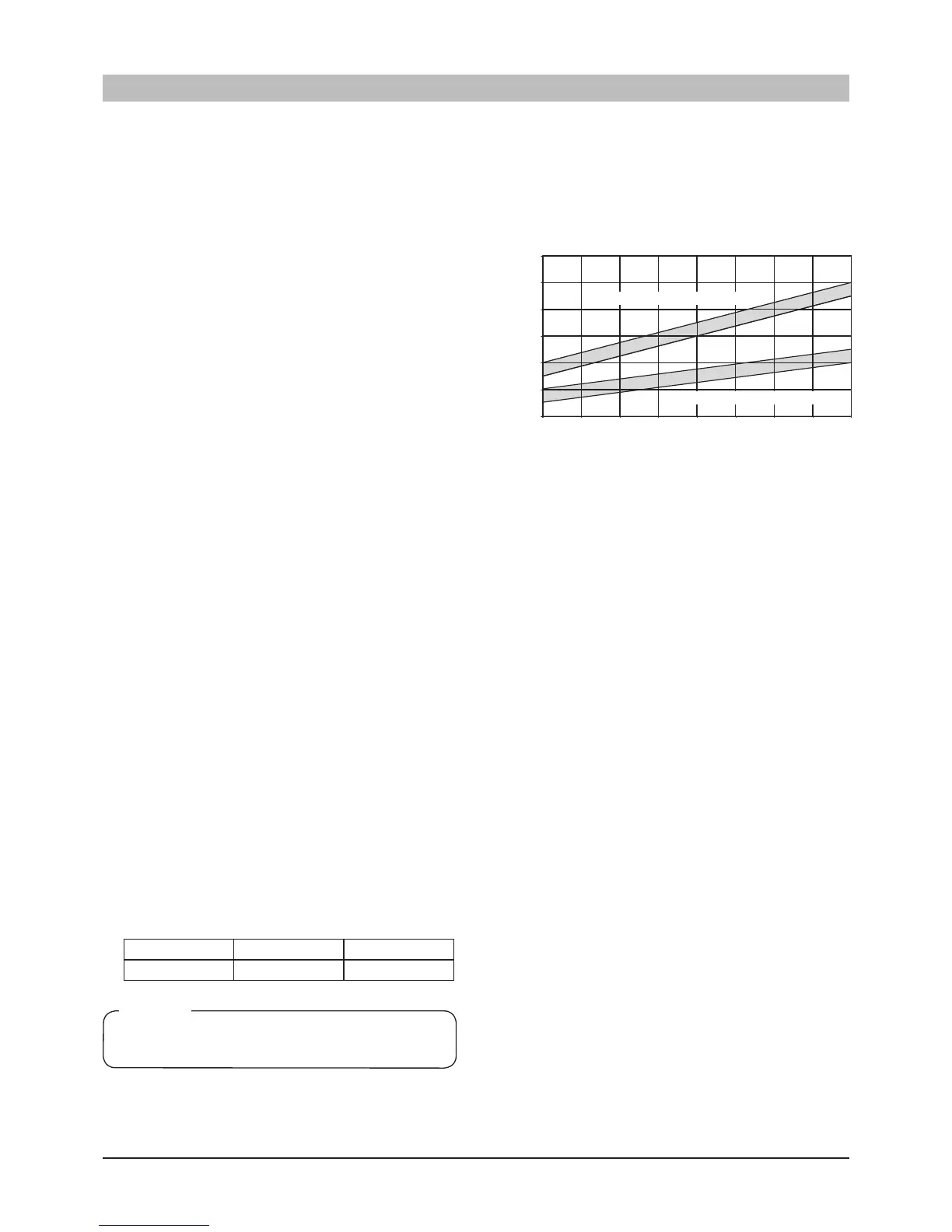
4. Check the supply and return line temperatures in Menu 2.5.
Adjust the circulation pump speed in Menu 2.1.5 so that the
difference between these temperatures is according to the
diagram below.
5. Select “Off” in Menu 9.6.2.
Setting system flow cooling
The factory setting 100% in Menu 2.2.5 is recommended.
Comfort setting heating
See page 46 for setting the Heating curve.
Comfort setting cooling
Cooling function is deactivated in the default setting. See page
49 how to activate it.
ForHM
S140VAwithfancoilapplication,itisalsonecessary
to change Cooing curve (menu 2.2.2) and Minimum supply
cooling (menu 2.2.4) settings as follows to obtain enough
capacity.
Coolingcurve
(2.2.2):3
Minimumsupplycooling(2.2.4):10
ForHMS140V,donotsettheMinimumsupplycoolinglower
than 18°C.
 Loading...