1General configuration
Contents of the Option equipment and special specification
1-6
1.7 Contents of the Option equipment and special specification
A list of all Optional equipments and special specifications are shown below.
Table 1-3 : The list of Option equipment and special specification
Item Type Specifications
Classificati
on
Note1)
Note1)In the classification column, ○ refers to an option,and □ to a Shipping special specifications.
Descripsion
Stopper for changing the
operating range of the J1
axis
1S-DH-03
Stopper part
+ side: +120, +90, +60, or +30 deg.
- side: -120, -90, -60, or -30 deg.
One each of the following can be
selected: ± 170 deg. are used for
the standard specification.
○
This must be installed by the customer.
Machine cable(Replaced
with shorter cable)
1S-02UCBL-03 For fixing
(Two sets for power and signal)
○・□
2m(A 2 m cable is supplied instead of the 5 m
cable that is supplied as standard)
Extended machine cable
(Extension type)
1S- □□ CBL-03 For fixing
(Two sets for power and signal)
○ 5, 10, 15m
1S- □□ LCBL-03 For bending
(Two sets for power and signal)
○ 5, 10, 15m
Solenoid valve set 1S-VD01-02 1 set ○
A solenoid valve set for the pneumatic hand
1S-VD02-02 2 set ○
1S-VD03-02 3 set ○
1S-VD04-02 4 set ○
Hand output cable 1S-GR35S-01
One terminal is not treated. ○
The cable is connected to the hand output con
-
nector by the customer.
Hand input cable 1S-HC25C-01
○
The cable is connected to the sensor by the cus
-
tomer.
Hand curl tube 1E-ST0402C For solenoid valve 1set.:Φ4x2 ○
Curl type air tube
1E-ST0404C For solenoid valve 1set.:Φ4x4 ○
1E-ST0406C For solenoid valve 1set.:Φ4x6 ○
1E-ST0407C For solenoid valve 1set.:Φ4x8 ○
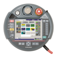
Teaching pendant R28TB Cable length 7m ○
With 3-position deadman switch/ IP 65
R28TB-15
Cable length 15m
(special specification)
○
Pneumatic hand interface
2A-RZ365 DO: 8 point (Sink type) ○
It is necessary when the hand output signal of the
robot arm is used. (Integrated in the controller.)
Parallel I/O Unit
2A-RZ361
DO: 32 point (Sink type)/
DI : 32 point (Sink type)
○
The unit for expansion the external input/output.
Electrical isolated Type
(100mA/Point)
External I/O cable
(For Parallel I/O Unit)
2A-CBL05 5m ○
Use to connect the external peripheral device to
the parallel input/output unit
2A-CBL15 15m ○
Personal computer cable
RS-MAXY-CBL
RS-232C cable 3m for PC-AT com
-
patible model
○
Use RS-AT-RCBL for the connection from the
expansion option box.
RS-AT-RCBL ○
Personal computer
Support software
3A-01C-WINE CD-ROM ○
MS-Windows98/2000/NT4.0/Me/XP
(With the simulation function)
Personal computer
Support software mini
3A-02C-WINE CD-ROM ○ MS-Windows98/2000/NT4.0/Me/XP
RT ToolBox2
(Personal computer Sup
-
port software)
3D-11C-WINE CD-ROM ○
MS-Windows2000/XP/Vista
(With the simulation function)
RT ToolBox2 mini
(Personal computer Sup
-
port software mini)
3D-12C-WINE CD-ROM ○ MS-Windows2000/XP/Vista
Expansion option box
Note2)
Note2)Required, if you use each interface
CR1-EB3
Up to three option cards can be
mounted
○ Install on the side of the controller
Extended serial interface
2A-RZ581-E
RS-232C x 1
RS-232C or RS-422 x 1
○ CR-EB3 is need.
CC-Link interface
2A-HR575-E
Local station (The local station alone
is supported.)
○
for MELSEC PLC with CC-Link connection. CR-
EB3 is need.
Ethernet interface 2A-HR533-E ETHERNET x 1 ○ CR-EB3 is need.
Additional axis interface
2A-RZ541-E
SSC x 1
Up to 8 axises can be added
○
MR-J2 servoAmplifer Unit connection. CR-EB3 is
need.
PROFIBUS interface
2A-RZ577-E PROFIBUS-DP slave ○
GSD file (FD) attached.
CR-EB3 is need.
Controller protection box
CR1B-MB IP54 ○ ・ □
The controller protection box is used to protect
the controller from an oil mist or other operating
environment
Instruction Manual
4S-MAP-103
A set of the instructions manual
bookbinding editions.
○

 Loading...

