2-7
Standard specifications
2Robot arm
2 Robot arm
2.1 Standard specifications
2.1.1 Standard specifications
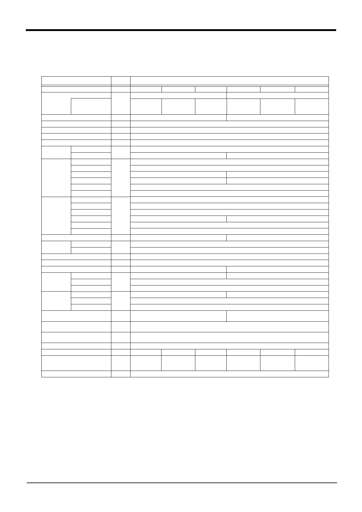
Table 2-1 : Tab Standard specifications of robot
Item Unit Specifications
Type RV-3S RV-3SC RV-3S-SM RV-3SJ RV-3SJC RV-3SJ-SM
Type of robot 6-axis 5-axis
Environment
Standard
(oil mist)
Clean
With the con
-
troller protec
-
tion box
Standard
(oil mist)
Clean
With the con
-
troller protec
-
tion box
Degree of freedom
6 5
Installation posture On floor, hanging,(against wall
Note1)
)
Note1) When used by mounting on the wall, a special specification that limits the operating range of the J1 axis will be used.
The operating range is limited by changing the mechanical stopper position and also by setting parameters.
Structure Vertical, multiple-joint type
Drive system AC servo motor (J1 to J3:and J5: with brake)
Position detection method Absolute encoder
Arm length
Upper arm
mm
245
Fore arm
270 300
Operating
range
Waist (J1)
Note1)
Degree
340 (-170 to +170)
Shoulder (J2)
225 (-90 to +135)
Elbow (J3)
191 (-20 to +171) 237 (-100 to +137)
Wrist twist (J4)
320 (-160 to +160) -
Wrist pitch (J5)
240 (-120 to +120)
Wrist roll (J6)
720 (-360 to +360)
Speed of
motion
Waist (J1)
Degree/
s
250
Shoulder (J2)
187
Elbow (J3)
250
Wrist twist (J4)
412 -
Wrist pitch (J5)
412
Wrist roll (J6)
660
Maximum resultant velocity
Note2)
Note2) This is the value on the hand flange surface when all axes are combined.
mm/sec
5,500 5,300
Load Maximum
Note3)
Note3) The maximum load capacity is the mass with the flange posture facing downword at the ± 10°limit.
kg
3.5
Rating
3
Pose repeatability
Note4)
Note4) The pose repeatability details are given in Page 8, "2.2.1 Pose repeatability"
mm
± 0.02
Ambient temperature ℃
0 to 40
Mass kg
37 33
Allowable
moment load
Wrist twist (J4)
N・m
5.83 -
Wrist pitch (J5)
5.83
Wrist roll (J6)
3.9
Allowable
inertia
Wrist twist (J4)
kg ・ m
2
0.137 -
Wrist pitch (J5)
0.137
Wrist roll (J6)
0.047
Note5)
Note5) When the optimum acceleration/deceleration mode is in effect, up to twice the specification value indicated here can
be set.
Arm reachable radius froot p-axis
center point
mm
642 641
Tool wiring
Note6)
Note6) The air hand interface (option) is required when the tool (hand) output is used.
Hand input 8 point, hand output 8 point, eight spare wires
(AWG#24(0.2mm
2
) with shielded)
Tool pneumatic pipes
Primary side: Φ6 × 2 (Base to fore arm section)
Secondary side
: Φ4 × 8 (Optional)
Supply pressure MPa
0.5 ± 10%
Protection specification
Note7)
Note7) The protection specification details are given in Page 9, "2.2.5 Protection specifications and working environment".
IP65 (all axes) - IP65 (all axes) IP65 (all axes) - IP65 (all axes)
Degree of cleanliness
Note8)
Note8) The clean specification details are given in Page 10, "2.2.6 Clean specifications". A down flow(0.3m/s or more) in the
clean room is the necessary conditions for the cleanliness.
-
10(0.3μm)
Internal suction
requirement
- -
10(0.3μm)
Internal suction
requirement
-
Painting color
Light gray (Equivalent to Munsell: 0.08GY7.64/0.81)
 Loading...


