3 Controller
Names of each part
3-38
3.2 Names of each part
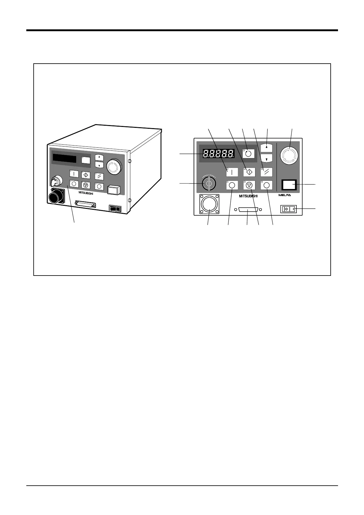
Fig.3-1 : Names of controller parts
1) POWER switch..................................... This turns the control power ON/OFF.
2) START button...................................... This executes the program and operates the robot. The program is run continuously.
3) STOP button ........................................ This stops the robot immediately. The servo does not turn OFF.
4) RESET button ...................................... This resets the error. This also resets the program's halted state and resets the program.
5) Emergency stop switch.................... This stops the robot in an emergency state. The servo turns OFF.
6) T/B remove switch............................ This is used to connect/disconnect the T/B without turning OFF the controller's control
power.
7) CHNGDISP button ............................. This changes the details displayed on the display panel in the order of "Override" → "Pro
-
gram No." → "Line No.".
8) END button............................................ This stops the program being executed at the last line or END statement.
9) SVO.ON button.................................... This turns ON the servo power. (The servo turns ON.)
10) SVO.OFF button............................... This turns OFF the servo power. (The servo turns OFF.)
11) STATUS NUMBER
(display panel)...................................... The alarm No., program No., override value (%), etc., are displayed.
12) T/B connection connector ......... This is a dedicated connector for connecting the T/B.
13) Personal computer
connection connector...................... This is an RS-232C specification connector for connecting the personal computer.
14) MODE key switch............................. This changes the robot's operation mode.
Note)
AUTO (Op.).................................. Only operations from the controller are valid. Operations for which the operation mode
must be at the external device or T/B are not possible.
TEACH .......................................... When the T/B is valid, only operations from the T/B are valid. Operations for which the
operation mode must be at the external device or controller are not possible.
AUTO (Ext.)................................. Only operations from the external device are valid. Operations for which the operation
mode must be at the T/B or controller are not possible.
15) UP/DOWN button ............................ This scrolls up or down the details displayed on the "STATUS. NUMBER" display panel.
2)
SVO OFF STOP
END
SVO ON
MODE
TEACH
AUTO
(Ext.)
AUTO
(Op.)
START
RESET
DOWN
UP
STATUS NUMBER
REMOVE T/B
EMG.STOP
CHANG DISP
7) 4) 15) 5)
6)
1)
11)
14)
12) 10) 13) 3)
8)
Front operation panel
9)
<Front> <Front side of operation panel>
 Loading...


