Hardware Installation
2-5
2.3 Requirements
The minimum installation requirements for a single-cell, peer-to-peer network (regardless of access
point model)
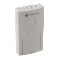
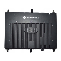
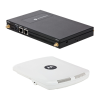
• An AP-5131 (either a dual or single radio model) or AP-5181 model access point
• 48 Volt Power Supply Part No. 50-14000-243R (AP-5131 models only) or Power Injector
(Part No. AP-PSBIAS-1P2-AFR or AP-PSBIAS-5181-01R)
• A power outlet
• Dual-Band Antennae
.
2.4 Access Point Placement
For optimal performance, install the access point (regardless of model) away from transformers,
heavy-duty motors, fluorescent lights, microwave ovens, refrigerators and other industrial equipment.
Signal loss can occur when metal, concrete, walls or floors block transmission. Install the access
point in open areas or add access points as needed to improve coverage.
Antenna coverage is analogous to lighting. Users might find an area lit from far away to be not bright
enough. An area lit sharply might minimize coverage and create dark areas. Uniform antenna
placement in an area (like even placement of a light bulb) provides even, efficient coverage.
Place the access point using the following guidelines:
• Install the access point at an ideal height of 10 feet from the ground.
• Orient the access point antennae vertically for best reception.
• Point the access point antenna(s) downward if attaching to the ceiling.
NOTE Though the AP-5181 can use the standard Power Injector solution (Part
No. AP-PSBIAS-1P2-AFR), Motorola recommends using the AP-5181
Power Tap (Part No. AP-PSBIAS-5181-01R), designed specifically for
outdoor deployments.
NOTE An AP-5131 or AP-5181 model access point optimally uses 2 antennae for
the single-radio model and 4 antenna for the dual-radio model. The
AP-5181 uses an antenna suite designed primarily for outdoor usage. For
more information, see Antenna Specifications on page A-5.

 Loading...