2-12
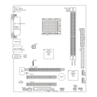
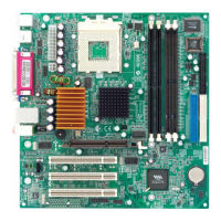
MS-6738 Micro ATX Mainboard
VGA Connector
The mainboard provides a DB 15-pin female connector to connect a
VGA monitor.
Pin Signal Description
1 RED
2 GREEN
3 BLUE
4 N/C
5 GND
6 GND
7 GND
8 GND
9 +5V
10 GND
11 N/C
12 SDA
13 Horizontal Sync
14 Vertical Sync
15 SCL
VGA Connector
(DB 15-pin)
1
5
11
15
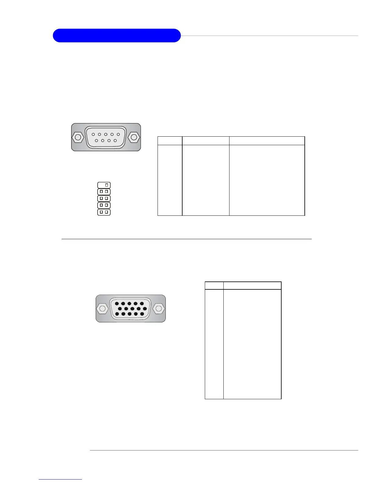
Serial Port Connectors: COM A & JCOM2 (Optional)
The mainboard offers two 9-pin male DIN connectors as serial port COM
A & JCOM2 on the board. The ports are 16550A high speed communication
ports that send/receive 16 bytes FIFOs. You can attach a serial mouse or
other serial devices directly to the connectors.
9-Pin Male DIN Connector
1 2 3 4 5
6 7 8 9
PIN SIGNAL DESCRIPTION
1 DCD Data Carry Detect
2 SIN Serial In or Receive Data
3 SOUT Serial Out or Transmit Data
4 DTR Data Terminal Ready
5 GND Ground
6 DSR Data Set Ready
7 RTS Request To Send
8 CTS Clear To Send
9 RI Ring Indicate
Pin Definition
JCOM 2
8
6
4
2
9
7
5
3
1
 Loading...