ROYAL evo
Page 68
Tip:
Threading the wires is easier if you slightly bend the
wire-ends and hold the stick in one of the corners.
3. Clip the wires in the holders designed for them on
the stick unit. Check that the wires have sufficient
freedom when the stick is deflected; they must not
be under tension at any point, and should not snag
anywhere.
4. Connect the bare wire ends to the appropriate
green screw-terminals on the main circuit board;
you will need a small slot-head screwdriver for this.
Remove the battery and push the wires in from the
battery-facing side of the terminals. It does not
matter which way round the wires are connected.
Fig. 1
Fig. 2
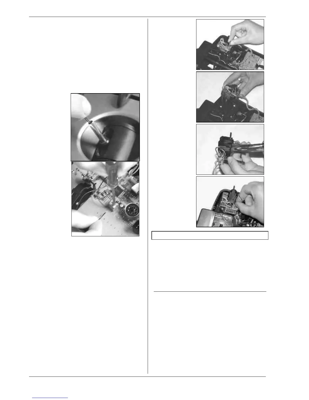
7.4.11. Installing the optional switches “P” and “K”
If you need extra functions 2-position switches can be
installed in the installation wells “P” and “K”. To fit them
the corresponding corner unit must be removed from
the transmitter:
1. Locate the TORX screwdriver (in a clip below the
aerial guide sleeve, close to the screen) and undo
the four TORX screws holding the appropriate stick
unit (Fig. 1).
2. Check that the switches are at the centre position,
then carefully withdraw the corner unit from the
transmitter. Remove the rotary knob (push-fit) from
the 3-D digi-adjustor when you withdraw the unit
(Fig. 2).
3. Use a small screwdriver to push out the blind cover
from the inside.
4. Fit the switch and secure it with the retaining nut
supplied (Fig. 3). Note the correct orientation: the
yellow wire should face the battery.
5. Re-install the corner unit, fit the retaining screws
and push the rotary knob back onto the 3-D digi-
adjustor (note correct position: internal index
shoulder). Connect the plug attached to the new
switch directly to the micro-connector on the cor-
ner unit (Fig. 4).
Fig. 1
Fig. 2
Fig. 3
Fig. 4
8. The transmitter battery
The ROYALevo is powered by a high-quality ready-made
battery pack consisting of 6 NiMH cells (Nickel-Metal-
Hydride) of the AA size. NiMH cells offer a much higher
energy density (capacity : weight) than NiCd (Nickel-
Cadmium) cells, and therefore provide longer operating
times for the same weight. They do require slightly dif-
ferent handling and greater care, especially when
charging.
8.1. Battery management in the ROYALevo
8.1.1. This is what we have already
Battery voltage display
Most transmitters show the battery voltage in graphic
or numeric form.
Battery alarm
An audible alarm indicates the voltage falling below the
minimum level. In many transmitters the minimum level
can be set by the user.
Both features are available in the ROYALevo of course.
(Battery alarm è 13.1.3.)

 Loading...