Instructions
Page 99
15.3.2. Parameter „Heading / Damping“
(Gyro gain)
In the gyro mode Control:
Gyro gain can only be adjusted manually using the
transmitter control Gyro (è 15.3.1 Mode à Control).
The set value of the Heading / Damping parameter
(gyro gain) has no effect in this gyro mode.
In the gyro mode Damping:
I is effective in the active model memory
4 allows separate values to be set for each flight
phase
Range 0 ... +100%
F can be assigned to 3-D digi-adjustor
The value for the parameter Damping (gyro gain) can be
set separately for each flight phase. The transmitter
control Gyro has no influence on the set values (è
15.3.1 Mode à Damping).
In the gyro mode Heading:
I is effective in the active model memory
4 allows two separate values to be set in each flight
phase, and called up using the Mix-1 switch
Range –100% (Heading) ... +100% (Damping)
F can be assigned to 3-D digi-adjustor
Two values for gyro gain can be set for each flight pha-
se. The switch Mix-1 is used to switch between the set-
tings (è 15.3.1.).
' TIP:
If you only want to be able to call up one gain setting in
a particular flight phase, regardless of the position of
the switch Mix-1, simply set the same values for both
switch positions.
The control Gyro has no influence on the set values.
! Note when using the gyro mixer in
Heading mode:
Before you operate the model, check carefully that the
gyro is working in accordance with the gain range you
have set:
1. Activate a flight phase in which
the gain range is 0 ... -100% (Heading).
2. Move the yaw (tail rotor) stick to either end-point
then back to neutral (centre).
If the yaw / tail rotor servo moves back to its starting
point, the gyro is working in Damping mode => the
direction of rotation of the Gyro channel must be re-
versed (è 16.1.1)
15.3.3. Parameter „Suppression“
I affects the active model memory
Range 2% ... 200%, increments of 2%
F can be assigned to 3-D digi-adjustor
The Suppression parameter is designed to provide a
user-variable linear reduction in gyro gain when the
associated transmitter control is moved to full travel.
This prevents the gyro system counteracting a deliber-
ate control command.
Values from 2% to 98% reduce the gain, but do not
suppress the gyro fully.
Values from 102% to 200% invoke full suppression be-
fore the yaw stick reaches ist end-position.
Suppression works in all gyro modes (Transmitter con-
trol, Damping, Heading) using the same value, regard-
less of flight phase.
Exception:
If gain is in the range 0 ... -100% (Heading).
! Note
Many gyro systems feature their own suppression func-
tion. In this case the suppression provided by the
transmitter must not be activated (Suppression => OFF).
Please read the operating instructions supplied with the
gyro.
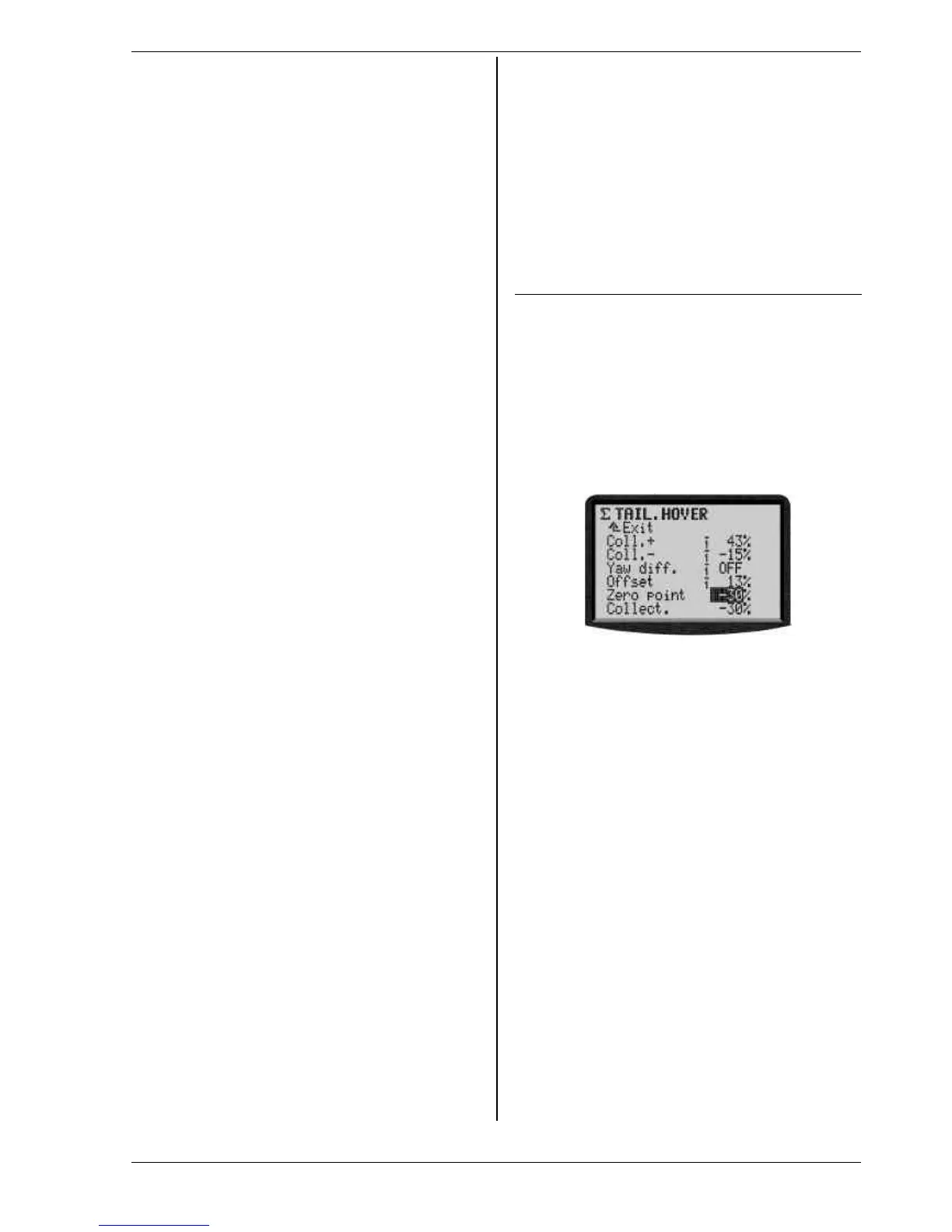
15.4. Sub-menu „Tail rotor“
(static tail rotor compensation/Revo-Mix)
The ROYALevo’s Tail rotor mixer provides what is known
as “static tail rotor compensation”. If the pilot sends a
command to the hovering helicopter causing it to climb
or descend, the torque which the tail rotor has to coun-
teract increases or reduces accordingly, and the model
reacts by swinging around its vertical axis. If correctly
set up, this mixer compensates for torque changes. This
helps to prevent the model swinging, and also eases the
work of the gyro system, with the net result that a high
level of stabilisation is possible. Four parameters are
required for this:
Collective Pitch+, Collective Pitch-, Offset, Zero point
! Notes
Before you start setting up this mixer all the settings
which involve the rotor head must be completed, in-
cluding the collective pitch curves. Before you make any
fine adjustments during the test flying programme the
throttle curve must be set up accurately. If you subse-
quently alter the throttle curve it is usually necessary to
correct the Tail rotor mixer settings too.
If you use a heading lock gyro the TAIL rotor mixer
must not be used or must be switched OFF!
Please read
our notes regarding the GYRO mixer (è 15.3.).
Preparation:
• The servo TAIL must be assigned in the menu *
Servo / Assignment (è 16.2.), otherwise the TAIL
mixer will not appear in the menu G Mixers.
• When calibrating the Tail servo a 2-point calibration
is sufficient (è 16.1.).
However, it is important to ensure that the servo is
not mechanically obstructed (stalled) at either end-
point (P1, P5).

 Loading...