2205Q2JE-HO-S6-N_2020.01.
Chapter 5 Maintenance and Inspection
SCV-series Screw Compressor 5.5 Reassembly
5-45
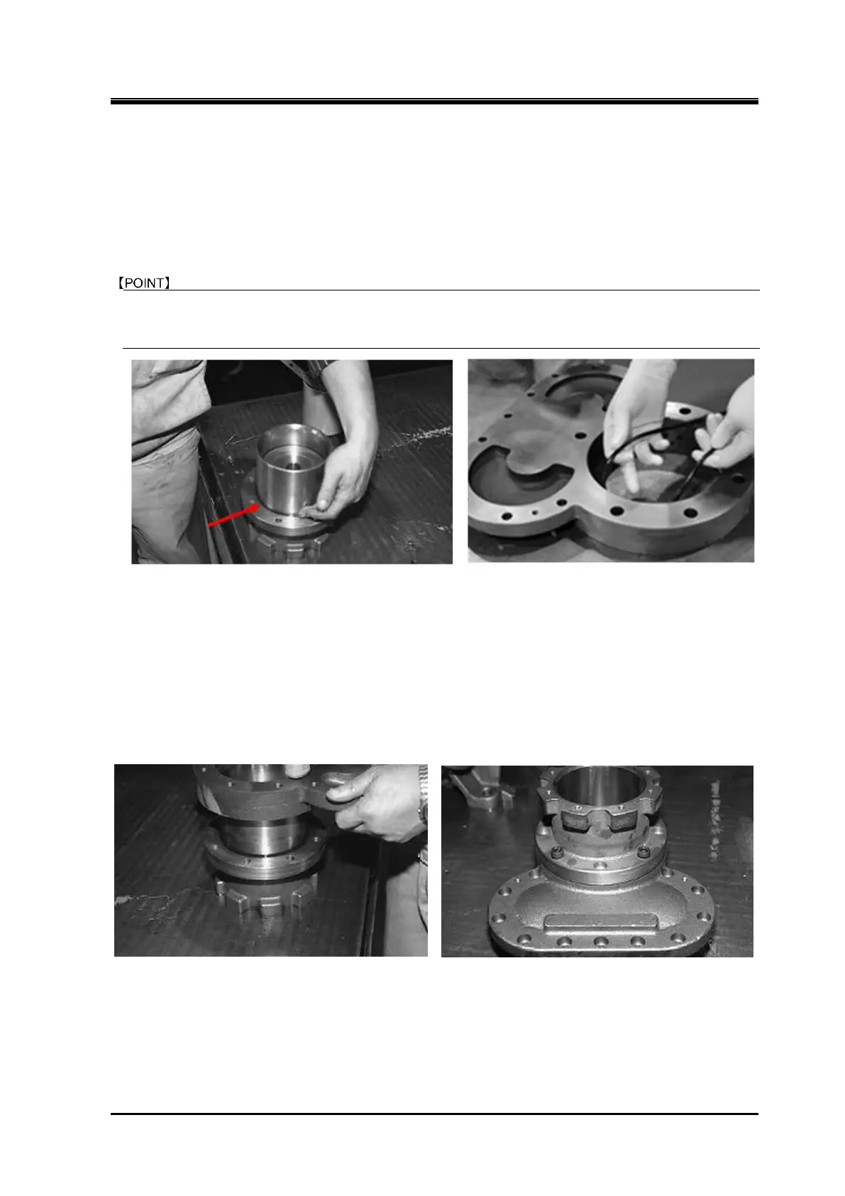
5.5.8 Balance Piston Cover and Unloader Cylinder
The assembly work of this block will become easier if the unloader cylinder is first installed on the
balance piston cover [22] and then the resulting assembly is installed on the suction cover [5].
a)
Install the O-ring [63] in the O-ring groove on the machined surface of the balance piston cover
along which the unloader cylinder is installed.
The fitting position of this O-ring [63] has been changed in Oct. 1996 to the current position shown in
following picture to the right from the previous flange surface of the unloader cylinder
(following
picture to the left).
b) Align the position of the balance piston cover with the unloader cylinder. As no gasket is used on the
mating flange between the balance piston cover and unloader cylinder, evenly and thinly apply
liquid gasket (made of special synthetic rubber) on the surface of the flange of the unloader cylinder
inside from the center of the bolt holes.
c) As the O-ring of the balance piston cover is already installed, lightly tap the flange surface with a
soft hammer to install it.
d) When joining the flanges, also align the bolt hole positions if any positioning steel rod is not used.
Then, insert two hexagon socket head cap screws [61] in the positions shown in the picture to the
right and to fasten the unloader cylinder to the balance piston cover.
e) Install the O-ring [73] in the O-ring groove on the tip of the unloader push rod [67], at the position
where the unloader piston is installed.
f) Install the unloader positioning spacer [420] in the unloader push rod [67], and push it to the bottom.
How to install the unloader positioning spacer varies depending on the compressor models as
shown in Table 5-11 in next page.
 Loading...