2205Q2JE-HO-S6-N_2020.01.
Chapter 5 Maintenance and Inspection
SCV-series Screw Compressor 5.5 Reassembly
5-38
5.5.4 Suction Cover and Side Bearings
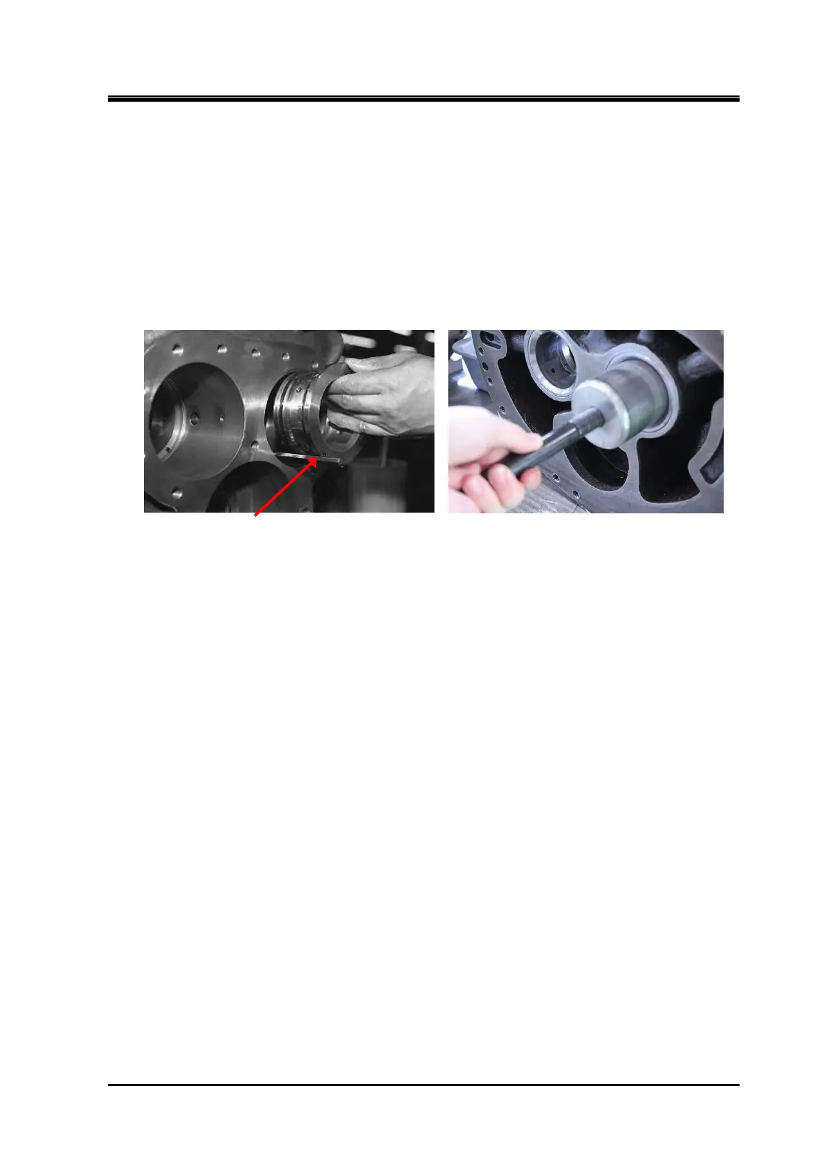
a) Similarly to the main bearing, the side bearing (O-ring type) [28] is machined to the size that will
allow light press fitting to the suction cover.
Press fit the bearing by aligning the notch position of the bearing with the spring pin [8] for
positioning the bearing driven-in on the suction cover. During the press fitting process, check that
the notch position of the bearing is at the pin position. If the position has been shifted, pull out the
bearing and try the press fitting process again.
b) After installing the bearing, insert the snap ring [29] to retain the bearing. Make sure that the snap
ring is fully seated in the ring groove either by pushing the ring with a guide bar or tapping the head
of the guide bar while applying the bar on the ring.
Aligning the Bearing position using Guide Bar Installing the Bearing using the Jig
c)
In case of 160 to 250V** models, after attaching the O-ring [9] to the O-ring groove located on the
unloader push rod passes parts of the suction cover, attach O-ring gland [326] with two O-rings
[326] at inner diameter.
In case of 320V*D models, attach the O-ring [9] and O-ring gland [326] after assembling the suction
cover and main rotor casing.
5.5.5 Balance Piston Sleeve
Install the balance piston sleeve to the M rotor side of the suction cover.
a) First, install the snap ring for the O-ring spacer [37], and then install the O-ring spacer [36].
b) After fitting the O-ring [35] in position, install the balance piston sleeve [33].
Insert the chamfered side of the balance piston sleeve towards the O-ring already placed.
c) In case of 160 to 250V** models, align the notch of the balance piston sleeve with the thread hole
on the suction cover. And then, screw the set screw [34] for the balance piston sleeve detent, and
attach a remaining set screw from the opposite side (F rotor side) to secure the set screw which is
attached earlier.
In case of 320V*D models, fit the spring pin provided on the outside diameter of the balance piston
sleeve into the notch in the suction cover for the balance piston sleeve detent.
d) Insert the snap ring [37] to retain the balance piston sleeve. As it should be difficult to fit the snap
ring into the groove due to the elastic force of the O-ring, either push the side of the ring by a guide
bar or tap the head of the guide bar to fit the ring securely into the groove.
 Loading...