2205Q2JE-HO-S6-N_2020.01.
Chapter 5 Maintenance and Inspection
SCV-series Screw Compressor 5.4 Disassembly and Inspection
5-22
f) Screw in two M8 eye bolts to the two jacking bolt threads on the balance piston cover, and separate
the balance piston cover with unloader cylinder from the suction cover.
g) Remove two fastening bolts [61], and separate the unloader cylinder and balance piston cover.
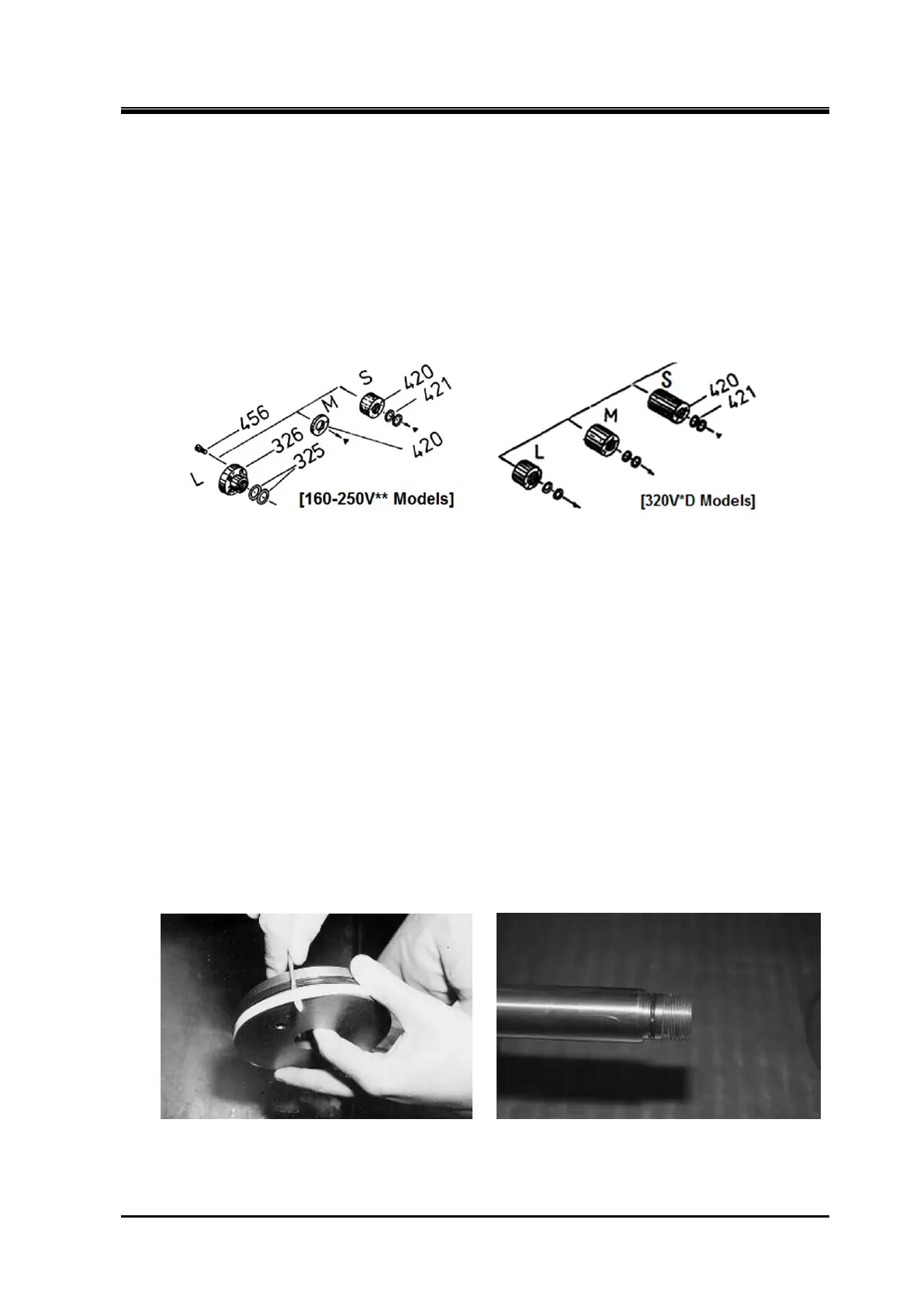
h) In case of SCV-series 320 models, i.e., VL* type, VM* type and VS* type are installed the unloader
piston spacer [420] with two O-rings [421].
In case of 160 to 250V**, VM* type is installed the unloader piston spacer [420] without O-ring [421],
VS* type is installed unloader piston spacer with two O-rings [421].
If your compressor is applicable above description, remove each part at this point.
, Figure 5-9 Unloader Piston Spacer and O-rings
5.4.4.2 Inspection
a) Both the O-ring [65] and cap seal [66] that are on the periphery of the unloader piston [64] must be
replaced by new ones.
b)
As it is often seen that the inside of the unloader cylinder has flaws or is contaminated by oil residue,
thoroughly clean the area and use fine sandpapers to finish the surface.
c)
Inspect the guide pin [68] on the tip of unloader push rod and replace it with a new one if scratches
and/or wear are found.
d)
Replace the O-rings [421] for unloader piston spacer, [73] at the tip of unloader push rod, [63] at the
connection between the balance piston cover and unloader cylinder.
Also, replace the lock washer [70] for fastening the unloader piston to unloader push rod and the
balance piston cover gasket [23].
e)
When large deformation is found in the lock nut [69] grooves which may be hit by a lock nut wrench,
replace the lock nut with a new one.
Removing the Cap Seal O-ring [63] at the tip of Unloader Push Rod
 Loading...