2205Q2JE-HO-S6-N_2020.01.
Chapter 5 Maintenance and Inspection
SCV-series Screw Compressor 5.4 Disassembly and Inspection
5-25
5.4.6 Bearing Cover
The bearing cover differs in shape between the D type models (with a bearing head for sideways
discharging) and the G type models (with a bearing head for downward discharging). The discharge
port is in an unsymmetrical location with the D type models, so the bearing cover has imbalanced
weight distribution between the right and left; this requires careful handling of the bearing cover during
its removal.
Make sure to take sufficient care to handle the heavy objects, and make better use of a
crane or chain block, etc., if necessary.
Dropping heavy objects may cause a large damage to workers and goods
5.4.6.1 Disassembly
a) Apply protective tape or cloth, etc. on the rotor axis surface to prevent from any damage during the
work.
b)
Remove the domed cap nut [522] and hexagon nut [453] of the Vi adjusting rod [444].
c)
Of the hexagon socket head cap screws fastening the bearing cover [18-1], [18-2], [18-3], replace
the two screws at the upper side of the bearing cover with stud bolts (headless safety bolts) and
then remove all the other screws.
d) Jacking bolt holes are provided at the 2 o’clock and 8 o’clock positions on the bearing cover (these
holes are plugged with vinyl caps at the time of shipment from the factory).
First place a container for catching oil under the bearing cover and then install the two of the
removed hexagon socket head cap screws into the jacking bolt holes and screw in them alternately
to create and widen the clearance between the bearing head and bearing cover. Oil will flow out as
the clearance is widened.
e)
The cover will come off the alignment pins located near the screws being turned in as the clearance
increases.
At this point, if the bearing cover is not properly supported, it may fall or drop down onto
the rotor shaft to cause damage on it.
On the 200, 250, 320 models, there are threaded holes at the top of the bearing
cover‘s flange. As the bearing cover is heavy, install the eye bolts in these threads to
lift the cover using a crane or a chain block with lifting tools to removing work.
5.4.6.2 Inspection
a) Check the alignment pins as they would have been bent when removing the bearing cover.
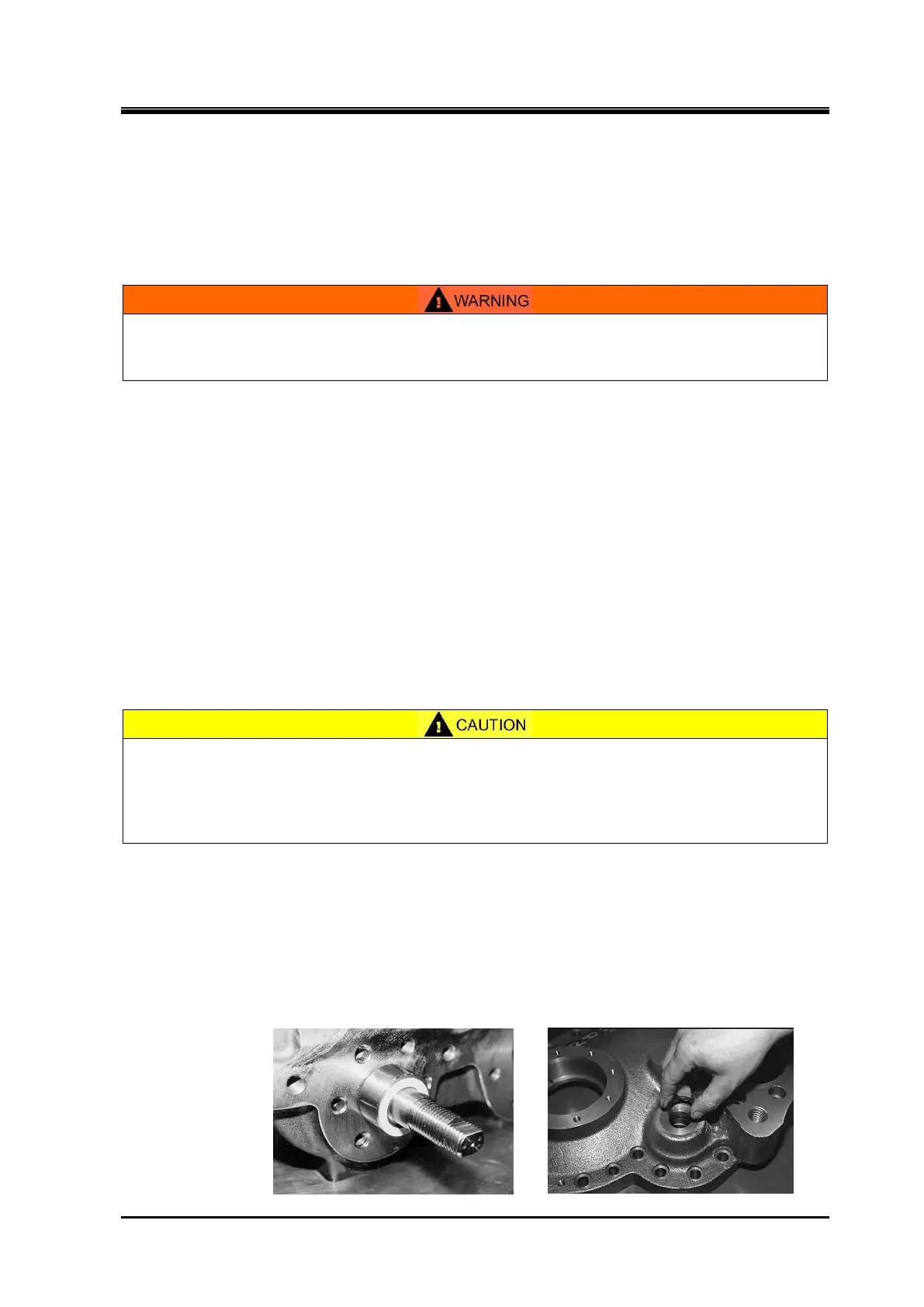
b)
Inspect the thrust washer [449] (as the white ring part shown in following picture to the left) of the Vi
adjusting rod. Replace the washer if it is defective.
c)
Always replace the bearing cover gasket [17] and the bearing cover side two O-rings [450] (following
picture to the right) of the Vi adjusting rod.
 Loading...