2205Q2JE-HO-S6-N_2020.01.
Chapter 5 Maintenance and Inspection
SCV-series Screw Compressor 5.3 Compressor Disassembly Preparation
5-12
5.3.5 Removal of the Compressor from Base Frame
The work to lift up or move the compressor must be performed by a qualified operator.
If the work is done by an unqualified operator, it may result in a dropping accident.
Never try to perform disassembly or assembly while the compressor is lifted in the air.
The main body or some part of the compressor can drop down on people below.
As the suction piping is located immediately above the compressor, lift up or partially remove the piping
such that it will not interfere with the lifting device.
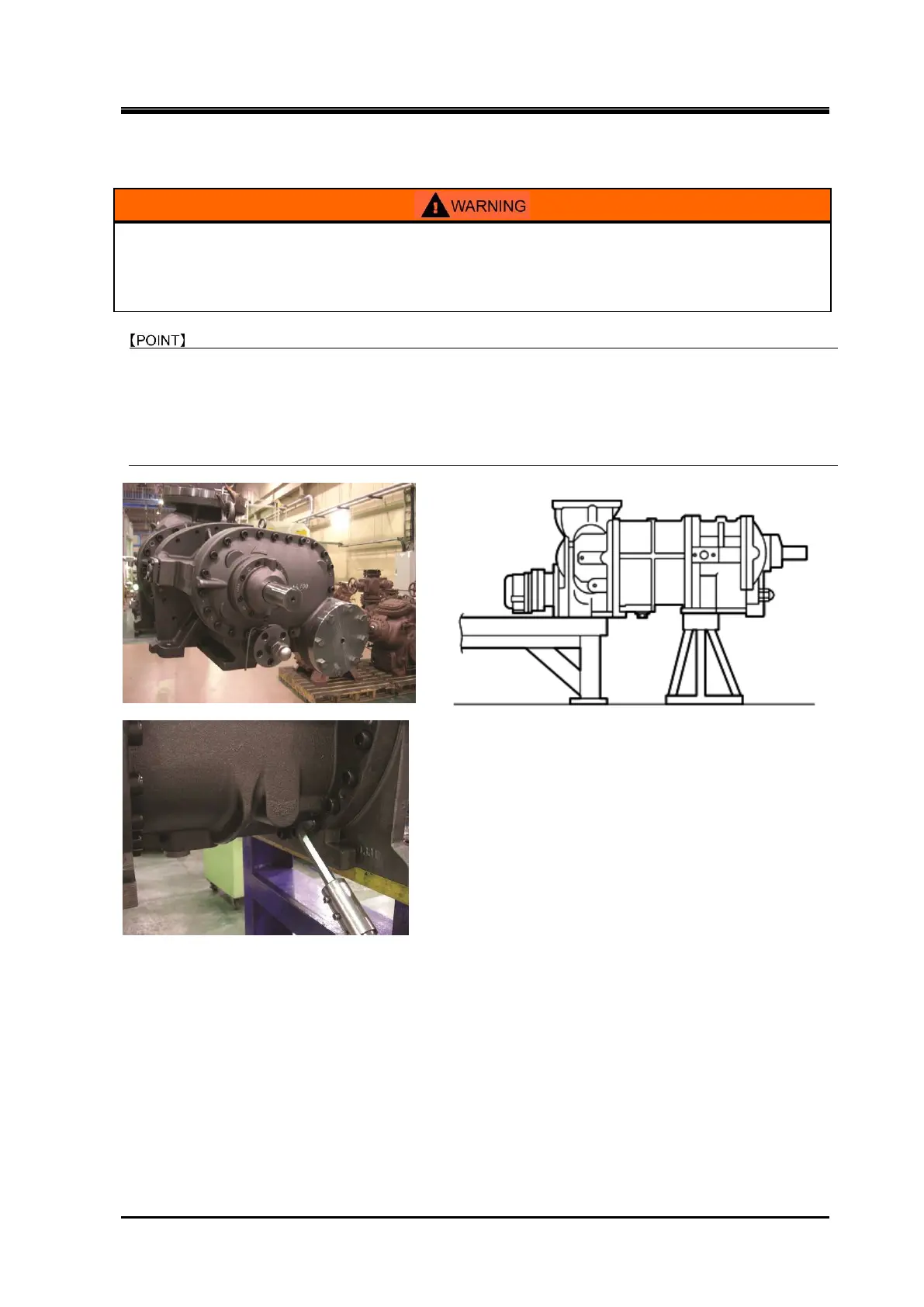
After lifting up the compressor, place it on a special stand to remove
hexagon head cap screws around
the bottom flange part. Instead of using the special stand, you can use the temporally stand which
same height as the workbench, i.e., place the leg part of the suction cover on t
he workbench and place
the leg part of bearing head on the temporally stand as shown in Figure 5-2.
a) Place the compressor on the special stand or use a temporary stand as shown in Figure 5-2.
Then remove 6 to 8 hexagon head cap screws around the bottom flange part tightened rotor
casing [1] to suction cover [5] / bearing head [11].
Note: After placing the compressor on the workbench, it is impossible to remove these lower bolts.
b) Remove the compressor onto the workbench. How to place the compressor on the workbench
varies according to the compressor models described below;
In case of a V*G type which has a discharge port facing sideways, the entire compressor can be
placed on the workbench without doing any special arrangement, as the flange is on the same
plane as the legs of the suction cover and bearing head.
In case of a V*D type which has a discharge port facing down and thus a discharge port flange
extending downward from the leg plane of the suction cover and bearing head, place the
compressor with the flange part outside of the workbench edge (see Figure 5-3 in next page).
Figure 5-2 In case of using temporary stand
 Loading...