2205Q2JE-HO-S6-N_2020.01.
Chapter 5 Maintenance and Inspection
SCV-series Screw Compressor 5.4 Disassembly and Inspection
5-26
5.4.7 Suction Cover and Side Bearings
If the work sequence is such that the thrust bearing block is disassembled first and then the suction
cover is removed, there is a risk that, when the suction cover is separated from the rotor casing, the
rotor may also be pull out and dropped. As such, in the procedure described in this manual, the suction
cover is removed first, and then the thrust bearing is disassembled.
In this procedure to remove the suction cover before disassembling the thrust bearing
block, it is necessary to sufficiently loosen the lock nut that are securing the thrust
bearing while the rotor is supported by both the main and side bearings, in order not to
damage the rotor during the disassembly process.
5.4.7.1 Disassembly
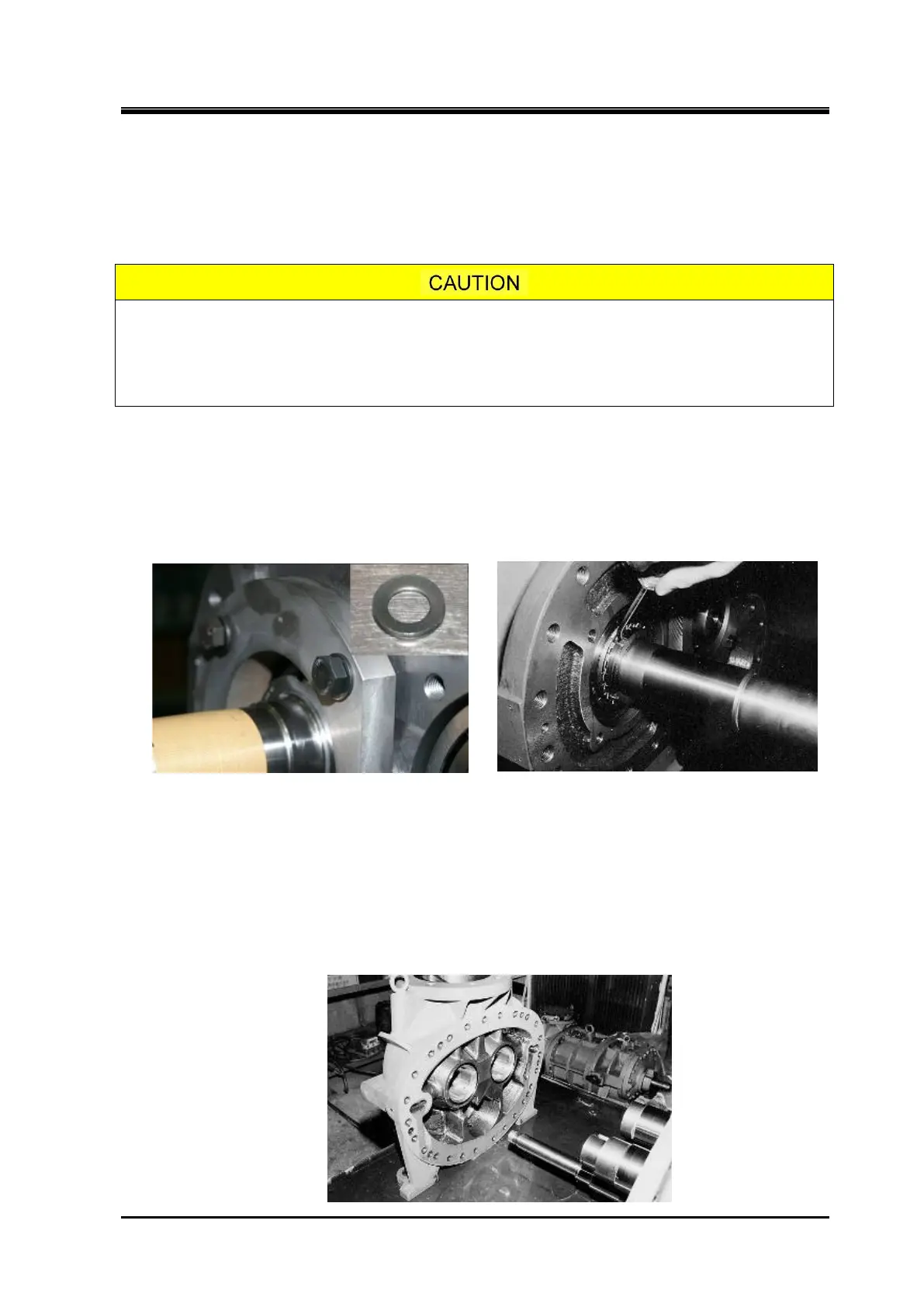
a) Remove the hexagon head bolts [45] and conical spring washers [46] that fasten the thrust bearing
gland [43]. Then, remove the thrust bearing gland.
b) Unbend the claws of the lock washer [40] holding the lock nut [39], which retains the inner race of
each thrust bearing on the rotor shaft and loosen the lock nut using a lock nut wrench.
Removing the Thrust Bearing Gland Unbend the Claw of the Lock Washer
c) Loosen and remove the hexagon socket head cap screws [2] securing the suction cover [5] to the
rotor casing [1].
d)
As the gasket [6] of the suction cover is sticking to the surface of the flange, screw two hexagon
socket head cap screws [2] that have been removed into the jacking threads in the rotor casing
flange to evenly push the suction cover. When some gap is observed between them, use a thin knife
or spatula to remove one side of the gasket from the surface.
e)
When it comes to the position the alignment pins are disengaged, pull out the suction cover at once
along the shaft axis.
 Loading...