2205Q2JE-HO-S6-N_2020.01.
Chapter 5 Maintenance and Inspection
SCV-series Screw Compressor 5.5 Reassembly
5-53
5.5.12 Unloader Indicator
The specifications of the unloader indicator for SCV-series has been changed from December 2014
Moriya factory production.
For details of the new indicator specifications indicator after change, refer to the separately dedicated
manual. In this manual, previous standard type indicator is the described.
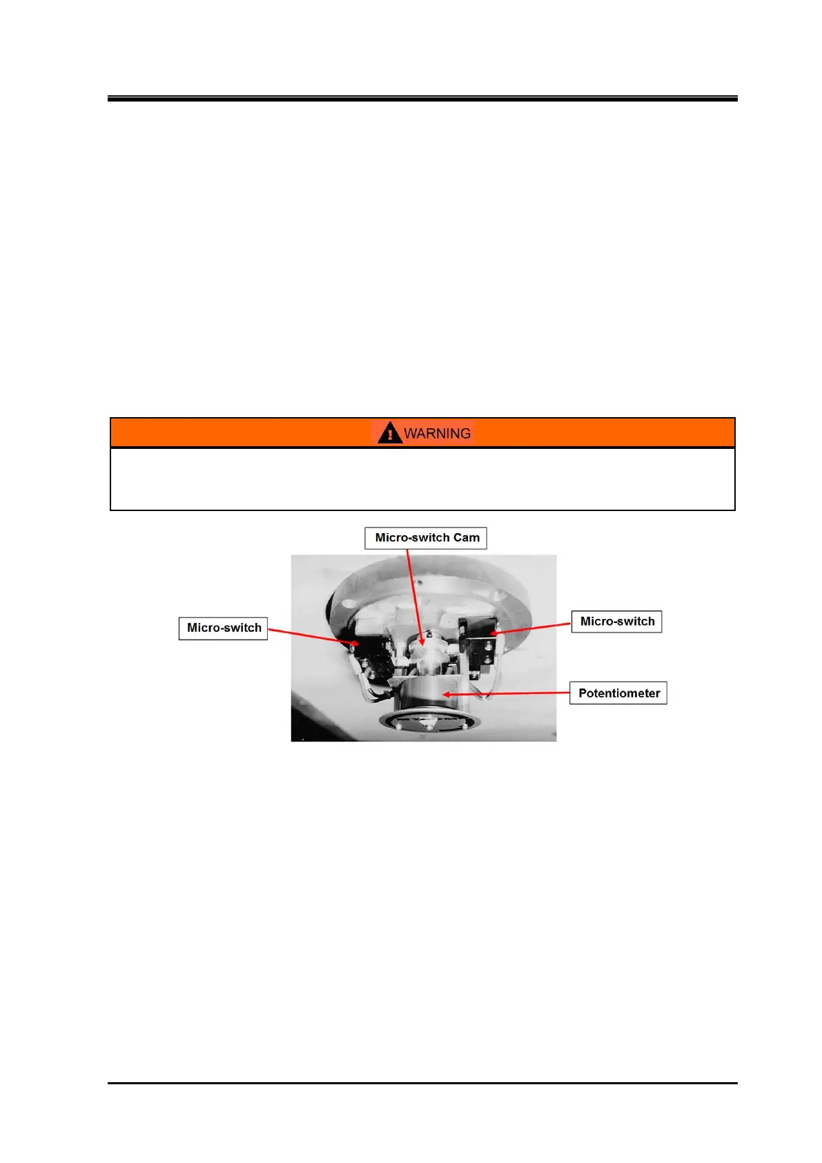
The unloader indicator is implemented with micro switches, micro switch cam, and potentiometer.
These parts are used to detect the change in the rotation angle of the indicator cam shaft, which
converts the axial position change of the unloader slide valve into rotational position change, convert
the change into an electric signal, and send the signal to the package unit and/or the controller of the
refrigeration system.
To check the unloader indicator after inspection, adjustment, or parts replacement, coordination with
the controller side will be required. Even in a case where the compressor is carried out of the
installation site for overhaul, the indicator assembly is often removed from the compressor (to be kept
at the site) and the inspection/adjustment and parts replacement are performed at the site. Thus, this
section provides a detailed procedure, which may be helpful after the reassembly work.
When removing the indicator block or performing inspection/adjustment or parts
replacement, be sure to shut down the control power and use lock-out and tag-out
procedures. If the power is not shut down, there is a risk of electric shock.
5.5.12.1 Potentiometer
The potentiometer of the indicator is a full-turn potentiometer, and it is used to feedback the unloader
slide valve position, in the form of electric signal, to the control system of the package unit or
refrigerator system to complete the feedback control system to enable non-incremental, indicated load
0 to 100% continuous control of the load. While the expected service life of the potentiometer will
significantly vary depending on the installation environment of the compressor (e.g. corrosive gas
atmosphere, moisture, etc.) and operational conditions (e.g. frequent partial load operations, frequent
start/stop operation, vibration, etc.), the potentiometer is a consumable part that requires regular
replacement according to the situation.
■ Inspection
a) Check at the terminal block that the lead wires of the potentiometer are not loosened.
b) Check for any crack or other defects in the soldering of the lead wires of the potentiometer.
c) Manually rotate the shaft of the potentiometer and measure the resistance value using a circuit
tester to check that the resistance value changes smoothly.
 Loading...