4-10 | ni.com
Chapter 4 Digital Input/Output and PFI
Digital Output Timing Signals
The cDAQ controller features the following DO timing signals:
• DO Sample Clock Signal*
• DO Sample Clock Timebase Signal
• DO Start Trigger Signal*
• DO Pause Trigger Signal*
Signals with an * support digital filtering. Refer to the PFI Filters section for more information.
DO Sample Clock Signal
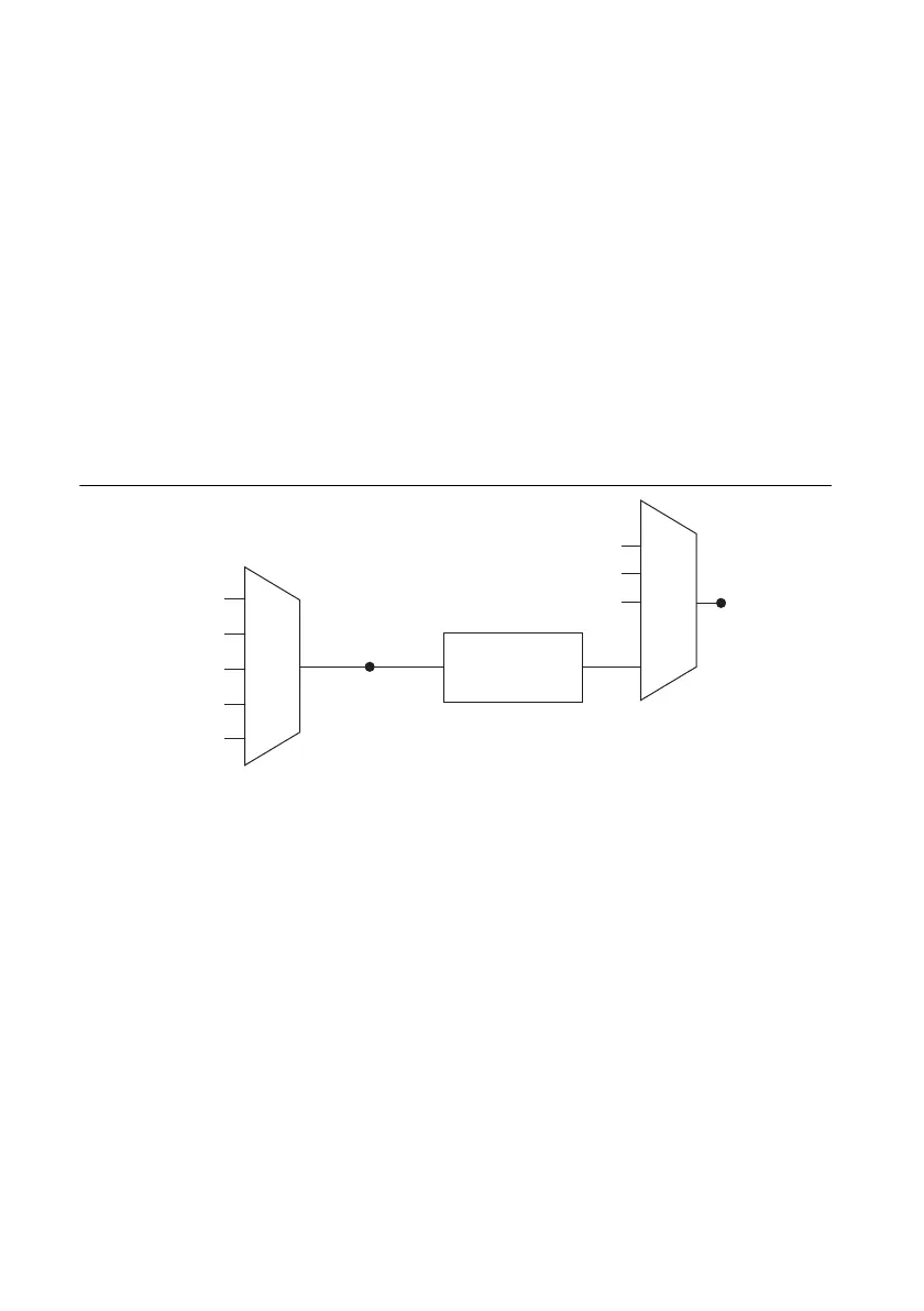
The DO Sample Clock (do/SampleClock) signals when all the digital output channels in the task
update. DO Sample Clock can be generated from external or internal sources as shown in
Figure 4-4.
Figure 4-4. Digital Output Timing Options
Routing DO Sample Clock to an Output Terminal
You can route DO Sample Clock to any output PFI terminal. DO Sample Clock is active high
by default.
DO Sample Clock Timebase Signal
The DO Sample Clock Timebase (do/SampleClockTimebase) signal is divided down to provide
a source for DO Sample Clock. DO Sample Clock Timebase can be generated from external or
internal sources, and is not available as an output from the controller.
Programmable
Clock
Divider
DO Sample Clock
Timebase
PFI
Analog Comparison Event
Ctr
n
Internal Output
DO Sample Clock
Analog Comparison
Event
20 MHz Timebase
80 MHz Timebase
PFI
100 kHz Timebase
 Loading...