© National Instruments | 1-21
NI cDAQ-9132/9133/9134/9135/9136/9137 User Manual
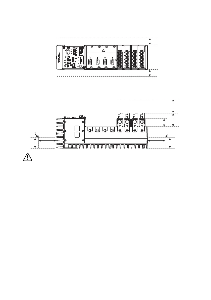
Figure 1-11. NI cDAQ-9133/9135/9137 Temperature, Cooling, and Cabling Dimensions
(NI cDAQ-9135 Shown)
Caution Your installation must meet the following requirements for space and
cabling clearance, as shown in Figures 1-10 and 1-11:
• Allow 25.4 mm (1.00 in.) on the top and the bottom of the controller for air
circulation.
• Allow 50.8 mm (2.00 in.) in front of modules for cabling clearance for common
connectors, such as the 10-terminal, detachable screw terminal connector.
Mounting the cDAQ Controller on a Panel
Directly mounting the cDAQ controller to a rigid surface is the only recommended method for
applications that are subject to high shock and vibration.
You can mount the cDAQ controller without a kit by screwing through a panel into the holes on
the back of the controller. Use M4 screws with a length suitable for the depth of the panel.
You can use the NI panel mount kit to mount the cDAQ controller on a flat surface. Refer to the
Cables and Accessories section for the accessory part number for your cDAQ controller.
Complete the following steps.
1. Fasten the mounting plate to the controller using a number 2 Phillips screwdriver and
M4 × 10 screws
1
. National Instruments provides these screws with the panel mount kit.
Tighten the screws to a maximum torque of 1.3 N · m (11.5 lb · in.).
NI 9263 NI 9263 NI 9263 NI 9263
25.4 mm (1.00 in.)
Cooling Dimensions
50.8 mm (2.00 in.)
Cabling Clearance
25.4 mm (1.00 in.)
Cooling Dimensions
50.8 mm (2.00 in.)
Measure Ambient
Temperature Here
27.8 mm
(1.09 in.)
63.5 mm
(2.50 in.)
63.5 mm
(2.50 in.)
38.1 mm
(1.50 in.)
38.1 mm
(1.50 in.)
Measure Ambient
Temperature Here
NI cDAQ-9135
NI CompactDAQ
USER1
SD
PUSH TO EJECT
NI 9263 NI 9263 NI 9263 NI 9263
25.4 mm (1.00 in.)
Cooling Dimensions
25.4 mm (1.00 in.)
Cooling Dimensions
50.8 mm (2.00 in.)
27.8 mm
(1.09 in.)
63.5 mm
(2.50 in.)
38.1 mm
(1.50 in.)
NI cDAQ-9135
NI CompactDAQ
 Loading...