© National Instruments | 6-21
cDAQ-9185/9189 User Manual
Channel Z behavior—when it goes high and how long it stays high—differs with quadrature
encoder designs. You must refer to the documentation for your quadrature encoder to obtain
timing of channel Z with respect to channels A and B. You must then ensure that channel Z is
high during at least a portion of the phase you specify for reload. For instance, in Figure 6-20,
channel Z is never high when channel A is high and channel B is low. Thus, the reload must
occur in some other phase.
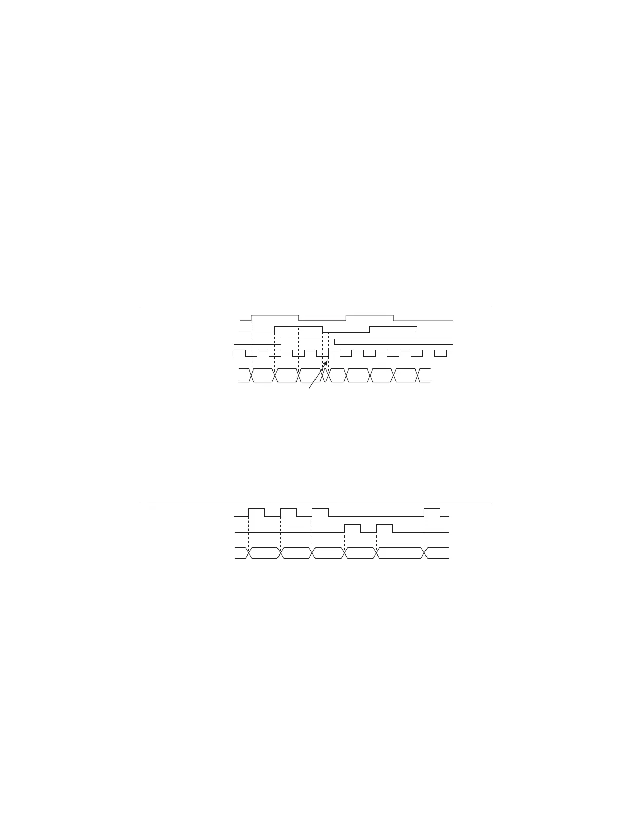
In Figure 6-20, the reload phase is when both channel A and channel B are low. The reload
occurs when this phase is true and channel Z is high. Incrementing and decrementing takes
priority over reloading. Thus, when the channel B goes low to enter the reload phase, the
increment occurs first. The reload occurs within one maximum timebase period after the
reload phase becomes true. After the reload occurs, the counter continues to count as before.
The figure illustrates channel Z reload with X4 decoding.
Figure 6-20. Channel Z Reload with X4 Decoding
Measurements Using Two Pulse Encoders
The counter supports two pulse encoders that have two channels—channels A and B.
The counter increments on each rising edge of channel A. The counter decrements on each rising
edge of channel B, as shown in Figure 6-21.
Figure 6-21. Measurements Using Two Pulse Encoders
For information about connecting counter signals, refer to the Default Counter/Timer Routing
section.
Buffered (Sample Clock) Position Measurement
With buffered position measurement (position measurement using a sample clock), the counter
increments based on the encoding used after the counter is armed. The value of the counter is
sampled on each active edge of a sample clock. The STC3 transfers the sampled values to host
memory using a high-speed data stream. The count values returned are the cumulative counts
Ch A
Ch B
Counter Value
5
6
A = 0
B = 0
Z = 1
Ch Z
Max Timebase
8
9
021743
Ch A
Ch B
Counter Value
2 3 54 344
Artisan Technology Group - Quality Instrumentation ... Guaranteed | (888) 88-SOURCE | www.artisantg.com

 Loading...