© National Instruments | 6-33
cDAQ-9185/9189 User Manual
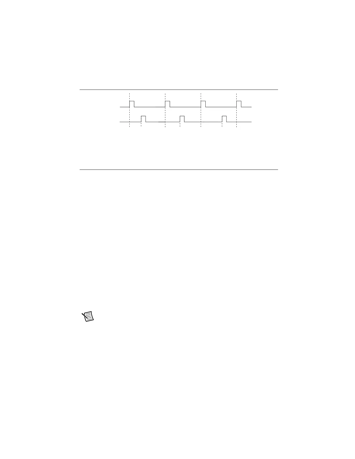
Figure 6-36. Pulse Generation for ETS
For information about connecting counter signals, refer to the Default Counter/Timer Routing
section.
Counter Timing Signals
The cDAQ chassis features the following counter timing signals:
• Counter n Source Signal
• Counter n Gate Signal
• Counter n Aux Signal
• Counter n A Signal
• Counter n B Signal
• Counter n Z Signal
• Counter n Up_Down Signal
• Counter n HW Arm Signal
• Counter n Sample Clock Signal
• Counter n Internal Output Signal
• Counter n TC Signal
• Frequency Output Signal
In this section, n refers to the cDAQ chassis Counter 0, 1, 2, or 3. For example, Counter n Source
refers to four signals—Counter 0 Source (the source input to Counter 0), Counter 1 Source (the
source input to Counter 1), Counter 2 Source (the source input to Counter 2), or Counter 3
Source (the source input to Counter 3).
Note All counter timing signals can be filtered. Refer to the PFI Filters section of
Chapter 5, Digital Input/Output and PFI, for more information.
Counter n Source Signal
The selected edge of the Counter n Source signal increments and decrements the counter value
depending on the application the counter is performing. Table 6-8 lists how this terminal is used
in various applications.
OUT
D1 D2 = D1 + ΔDD3 = D1 + 2ΔD
GATE
Artisan Technology Group - Quality Instrumentation ... Guaranteed | (888) 88-SOURCE | www.artisantg.com

 Loading...