6-24 | ni.com
Chapter 6 Counters
falling) edges on the Source input occurring between an active edge of the Gate signal and an
active edge of the Aux signal. The counter then stores the count in the FIFO on a sample clock
edge. On the next active edge of the Gate signal, the counter begins another measurement. The
STC3 transfers the sampled values to host memory using a high-speed data stream.
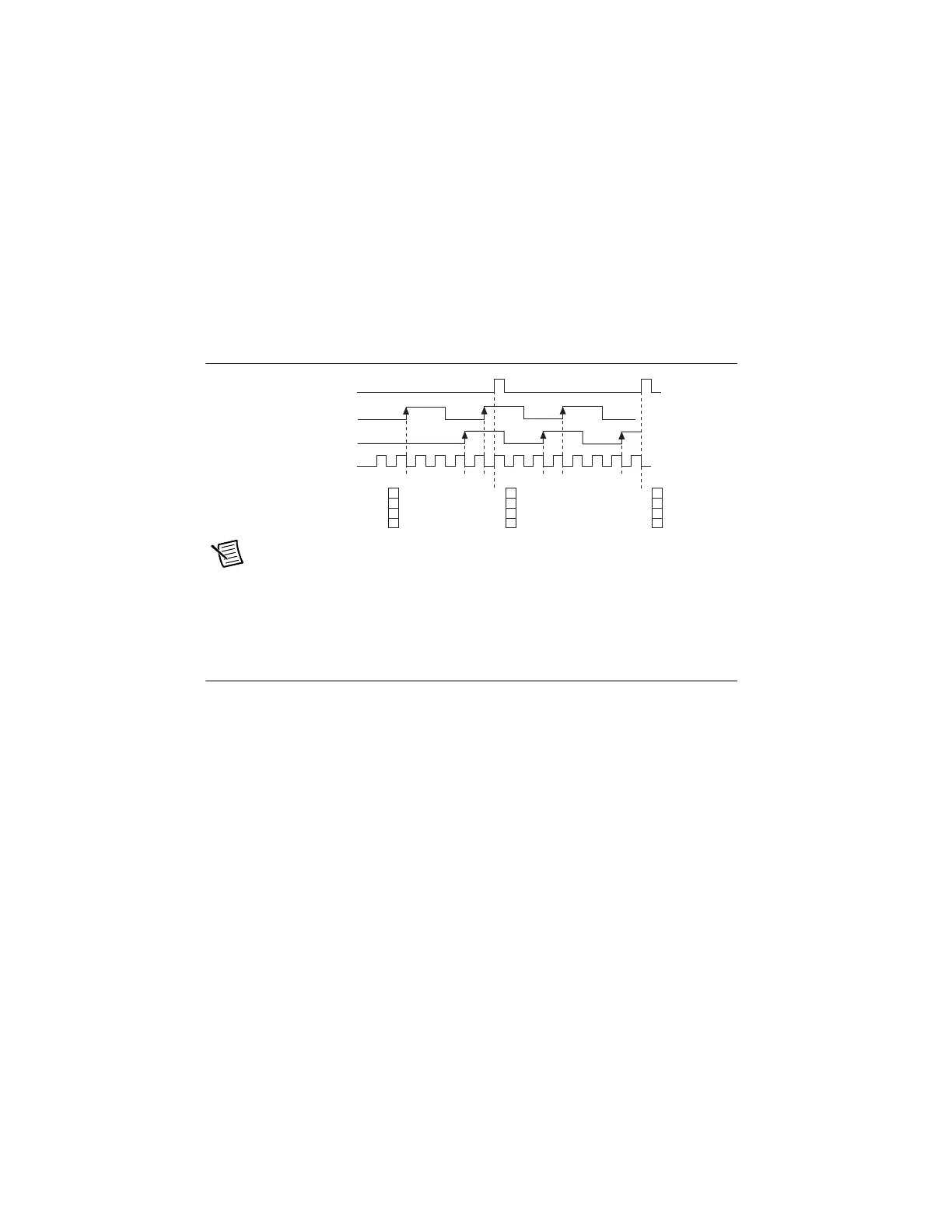
Figure 6-25 shows an example of a sample clocked buffered two-signal separation
measurement.
Figure 6-25. Sample Clocked Buffered Two-Signal Separation Measurement
Note If an active edge on the Gate and an active edge on the Aux does not occur
between sample clocks, an overrun error occurs.
For information about connecting counter signals, refer to the Default Counter/Timer Routing
section.
Counter Output Applications
The following sections list the various counter output applications available on the cDAQ
chassis:
• Simple Pulse Generation
• Pulse Train Generation
• Frequency Generation
• Frequency Division
• Using the Watchdog Timer
• Pulse Generation for ETS
Simple Pulse Generation
Refer to the following sections for more information about the cDAQ chassis simple pulse
generation options:
• Single Pulse Generation
• Single Pulse Generation with Start Trigger
SOURCE
Counter Value
Buffer
AUX
GATE
123 12 3 123
3 3
3
Sample
Clock
Artisan Technology Group - Quality Instrumentation ... Guaranteed | (888) 88-SOURCE | www.artisantg.com

 Loading...