© National Instruments | 1-17
cDAQ-9185/9189 User Manual
Tip Before using any of these mounting methods, record the serial number from the
back of the cDAQ chassis so that you can identify the cDAQ chassis in MAX. You
will be unable to read the serial number after you mount the cDAQ chassis.
Mounting Requirements
Your installation must meet the following requirements for cooling and cabling clearance.
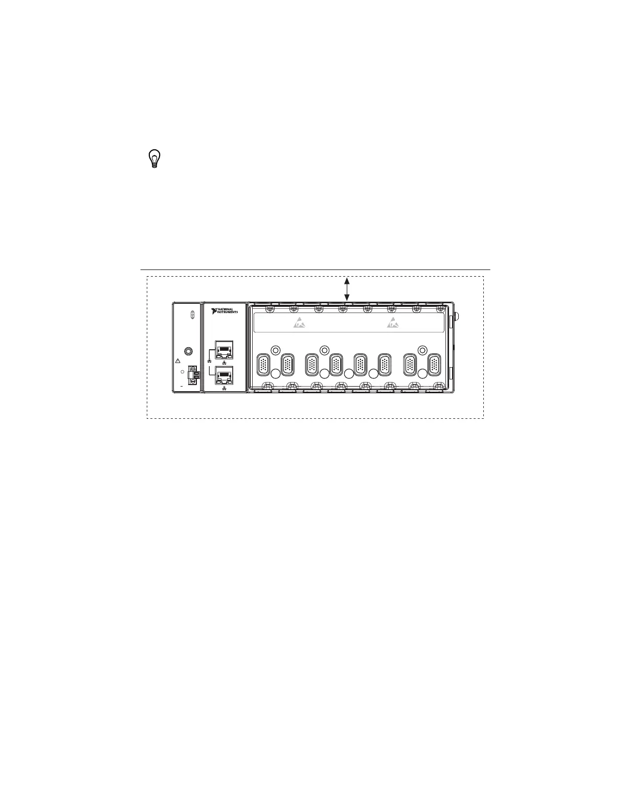
Allow 25.4 mm (1.00 in.) on all sides of the cDAQ chassis for air circulation, as shown in the
following figure.
Figure 1-12. Figure 9. cDAQ Chassis Cooling Dimensions (cDAQ-9189 Shown)
Allow the appropriate space in front of C Series modules for cabling clearance, as shown in the
following figure. The different connector types on C Series modules require different cabling
clearances. For a complete list of cabling clearances for C Series modules, visit
ni.com/info
and enter the Info Code crioconn.
25.4 mm (1.00 in.)
All Around
Cooling Dimensions
LINK/LINK/
ACTACT
10/100/10/100/
10001000
1
2
LINK/LINK/
ACTACT
10/100/10/100/
10001000
NI CompactDAQ
NI cDAQ-9189
POWER
STATUS
ACTIVE
PFI 0
RESET
INPUT
DO NOT SEPARATE
CONNECTORS
WHEN ENERGIZED
IN HAZARDOUS
LOCATIONS
9-30 V
16 W MAX
SYNC
V
C
C
V
12345678
Artisan Technology Group - Quality Instrumentation ... Guaranteed | (888) 88-SOURCE | www.artisantg.com

 Loading...