1-2 | ni.com
Chapter 1 NI 651x Fundamentals
If the DAQ device does not appear in MAX, use the following troubleshooting guidelines.
• Verify that you are using the correct version of NI-DAQ (NI-DAQ 7.3 or later). To
download the most recent National Instruments drivers, go to ni.com/drivers.
• Press <F5> to refresh the MAX window, or close and re-open MAX.
• Reboot the computer.
• Power off and unplug the computer or chassis, and install the device in a different slot.
Refer to the DAQ Getting Started Guide for installation instructions and safety guidelines.
NI 651x Functional Overview
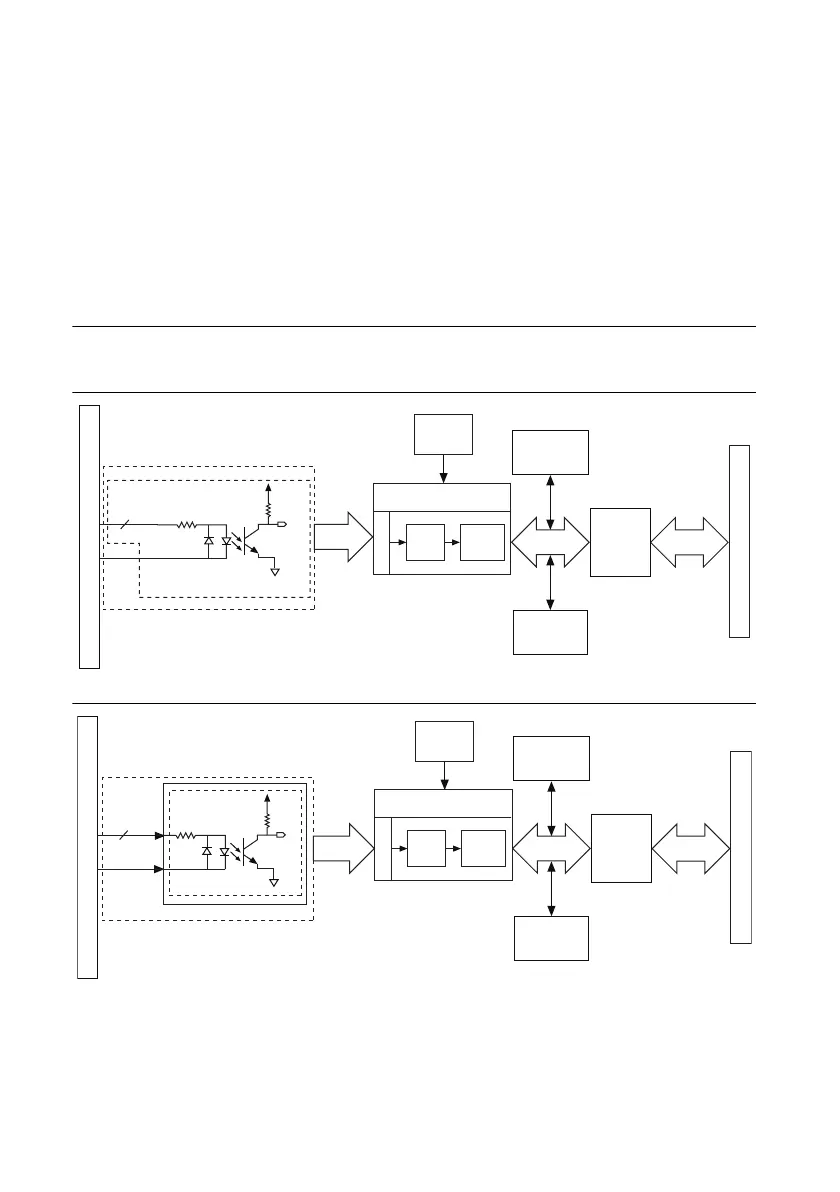
The following block diagrams illustrate the key functional components of the NI 651x devices.
Figure 1-1. NI 6510 Block Diagram
Figure 1-2. NI 6511 Block Diagram
PCI Bus
Industrial Digital
Input Control FPGA
Input Lines
Change
Detection
Digital
Filtering
Data/Control
PCI Bus
Interface
Data/Control
Flash
Memory
Configuration
Control
I/O Connector
32
COM
PX.<0..7>
VCC
x32 Bank Isolated Input Channels
DI
10 MHz
Clock
32 Digital
Inputs
I/O Connector
PCI/PXI/CompactPCI Bus
Industrial Digital
Input Control FPGA
Input Lines
Change
Detection
Digital
Filtering
Data/Control
PCI Bus
Interface
Data/Control
Flash
Memory
Configuration
Control
8
PX.COM
PX.<0..7>
Vcc
x8 Bank Isolated Digital Input Ports
x8 Inputs per Port
DI
10 MHz
Clock
64 Digital
Inputs

 Loading...


