© National Instruments | 3-21
NI 651x User Manual
Signal Descriptions
NI 6510 Signal Descriptions
NI 6511 Signal Descriptions
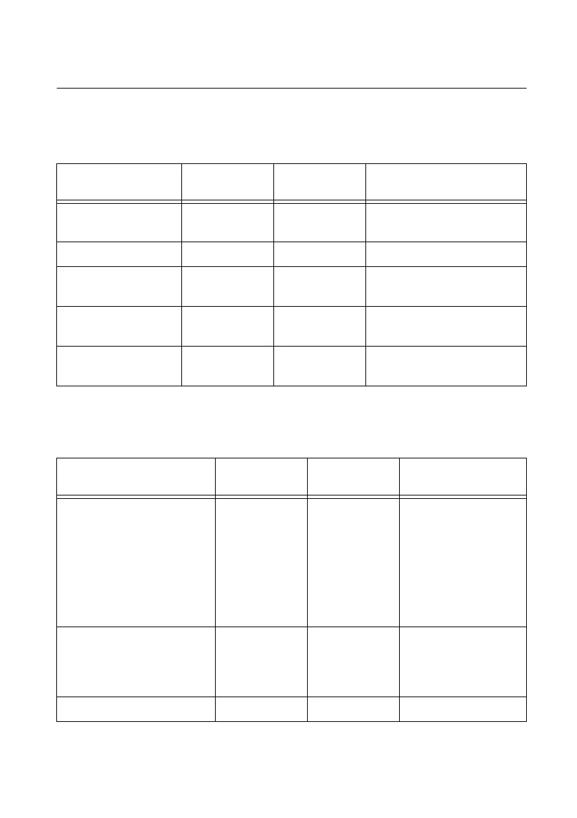
Table 3-1. NI 6510 Signal Descriptions
Pin Number Signal Name
Input or
Output
Signal Description
1, 2, 3, 4, 20, 21, 22,
23
P0.<0..7> Input Data lines for port 0
5, 14, 19, 28, 37 COM Input Common lines for all ports
6, 7, 8, 9, 24, 25, 26,
27
P1.<0..7> Input Data lines for port 1
10, 11, 12, 29, 30, 31,
32
P2.<0..7> Input Data lines for port 2
15, 16, 17, 18, 33, 34,
35, 36
P3.<0..7> Input Data lines for port 3
Table 3-2. NI 6511 Signal Descriptions
Pin Number Signal Name
Input or
Output
Signal Description
1, 2, 3, 4, 5, 6, 7, 8, 13, 14,
15, 16, 17, 18, 19, 20, 26, 27,
28, 29, 30, 31, 32, 33, 38, 39,
40, 41, 42, 43, 44, 45, 51, 52,
53, 54, 55, 56, 57, 58, 63, 64,
65, 66, 67, 68, 69, 70, 76, 77,
78, 79, 80, 81, 82, 83, 88, 89,
90, 91, 92, 93, 94, 95
P<0..7>.<0..7> Input Data lines for ports
0 through 7
9, 10, 11, 12, 21, 22, 23, 24,
34, 35, 36, 37, 46, 47, 48, 49,
59, 60, 61, 62, 71, 72, 73, 74,
84, 85, 86, 87, 96, 97, 98, 99
P<0..7>.COM Input Common lines for
ports 0 through 7
25, 50, 75, 100 NC — No connection

 Loading...


