© National Instruments | 4-9
NI 651x User Manual
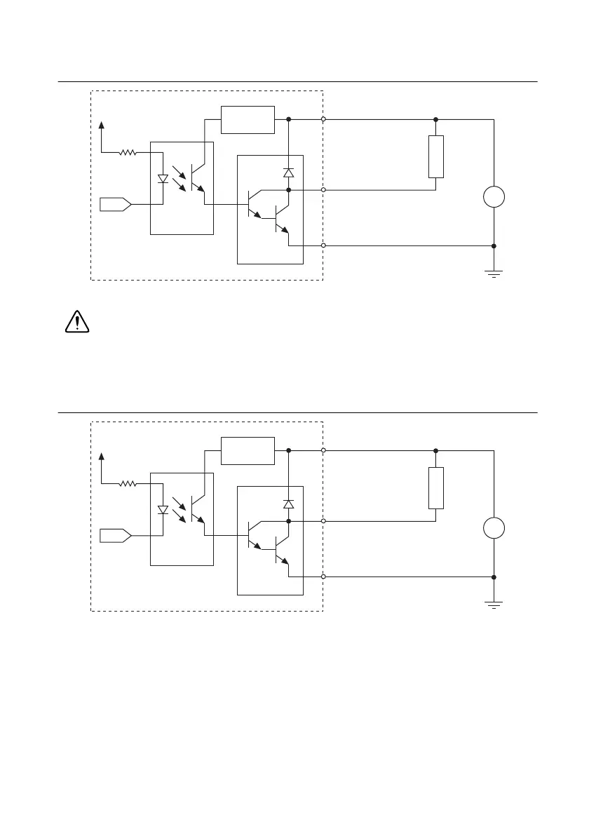
Figure 4-13. NI 6517 Output Signal Connection Example
Caution Make sure that OUT.COM (VCC) is connected to the positive pole of the
power supply and that GND is connected to the negative pole of the power supply.
Failure to do so could permanently damage the NI 6519 device and the power supply
if it is not protected.
Figure 4-14. NI 6519 Output Signal Connection Example
Distributing Current (NI 6517/6519 Only)
In applications that drive many high-current loads, a large amount of current must be returned
on the GND pins. When connecting the NI 6517/6519 to multiple loads, physically connect to
all GND pins on the device, as shown in Figure 4-15 and Figure 4-16. Connecting to all GND
pins distributes the current evenly among the GND pins and lowers the amount of current driven
on any single cable wire and on the accessory terminals.
Voltage
Regulator
COM (VCC)
P<0..3>.<0..7>
GND
+
–
DC
LOAD
+5 V ~ +30 V
Output
Photocoupler
+3.3 V
NI 6517
Darlington
Driver
Voltage
Regulator
OUT.COM (VCC)
P<2..3>.<0..7>
GND
+
–
DC
LOAD
+5 V ~ +30 V
Output
Photocoupler
+3.3 V
NI 6519
Darlington
Driver

 Loading...


