3-22 | ni.com
Chapter 3 Digital I/O
NI 6512 Signal Descriptions
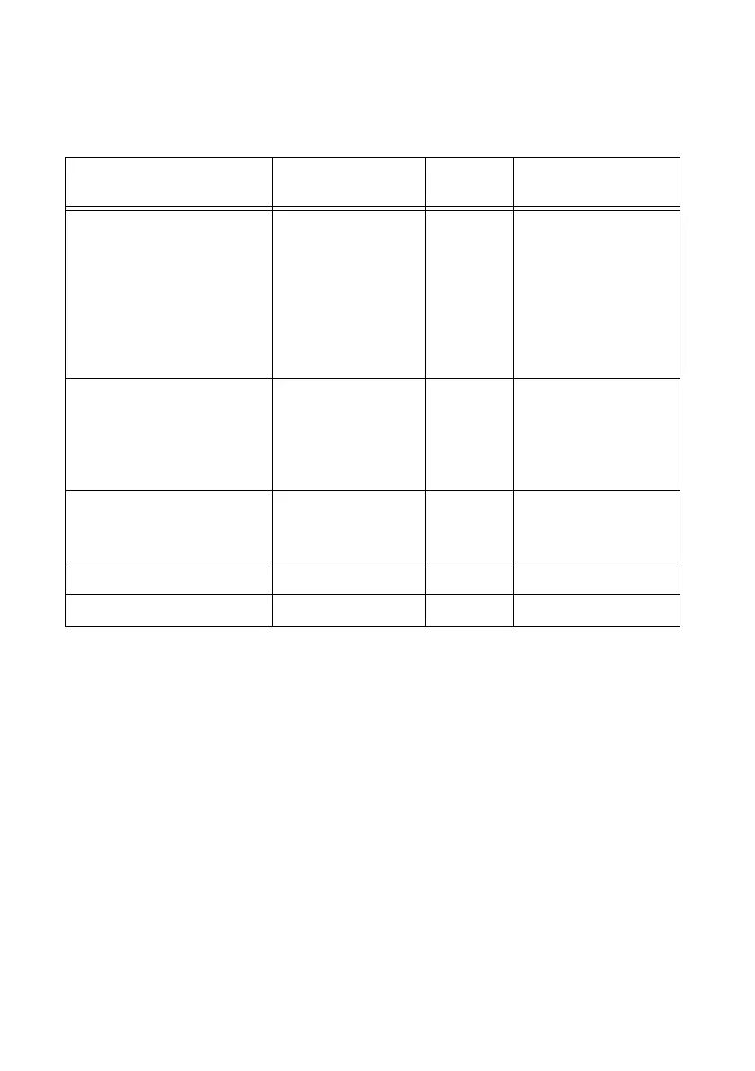
Table 3-3. NI 6512 Signal Descriptions
Pin Number Signal Name
Input or
Output
Signal Description
1, 2, 3, 4, 5, 6, 7, 8, 13, 14,
15, 16, 17, 18, 19, 20, 26, 27,
28, 29, 30, 31, 32, 33, 38, 39,
40, 41, 42, 43, 44, 45, 51, 52,
53, 54, 55, 56, 57, 58, 63, 64,
65, 66, 67, 68, 69, 70, 76, 77,
78, 79, 80, 81, 82, 83, 88, 89,
90, 91, 92, 93, 94, 95
P<0..7>.<0..7> Output Data lines for ports
0 through 7
9, 21, 34, 46, 59, 71, 84, 96 P<0..7>.COM
(GND)
Input Ground for ports
0 through 7;
isolated from the
computer power
supply
10, 11, 12, 22, 23, 24, 35, 36,
37, 47, 48, 49, 60, 61, 62, 72,
73, 74, 85, 86, 87, 97, 98, 99
P<0..7>.VCC Input Power lines for ports
0 through 7
25, 75 NC — No connection
50, 100 P<6..7>.+5V Output +5 V for ports 6 and 7

 Loading...


