EasyManuals Logo
Home>National Instruments>I/O Systems>NI PCI-6510

National Instruments NI PCI-6510 User Manual

National Instruments NI PCI-6510
68 pages
To Next Page IconTo Next Page
To Previous Page IconTo Previous Page
Page #51 background imageLoading...
Page #51 background image
© National Instruments | 4-5
NI 651x User Manual
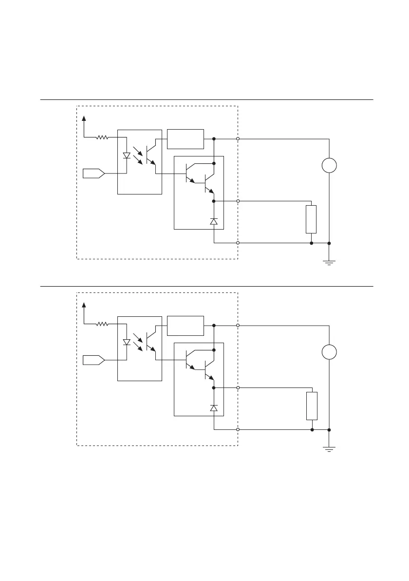
Output Signal Connection Example (Sourcing Current)
The following figures show examples of driving a load with the photocouplers and Darlington
arrays (sourcing current).
Figure 4-5. NI 6512 Output Signal Connection Example
Figure 4-6. NI 6514 Output Signal Connection Example
Voltage
Regulator
P<0..7>.COM (GND)
P<0..7>.<0..7>
+
DC
LOAD
+5 V ~ +30 V
Output
Photocoupler
+3.3 V
P<0..7>.VCC
NI 6512
Darlington
Driver
Voltage
Regulator
P<4..7>.COM (GND)
P<4..7>.<0..7>
+
DC
LOAD
+5 V ~ +30 V
Output
Photocoupler
+3.3 V
P<4..7>.VCC
NI 6514
Darlington
Driver

Table of Contents

Questions and Answers:

Question and Answer IconNeed help?

Do you have a question about the National Instruments NI PCI-6510 and is the answer not in the manual?

National Instruments NI PCI-6510 Specifications

General IconGeneral
BrandNational Instruments
ModelNI PCI-6510
CategoryI/O Systems
LanguageEnglish

Related product manuals