4-6 | ni.com
Chapter 4 Power Connections
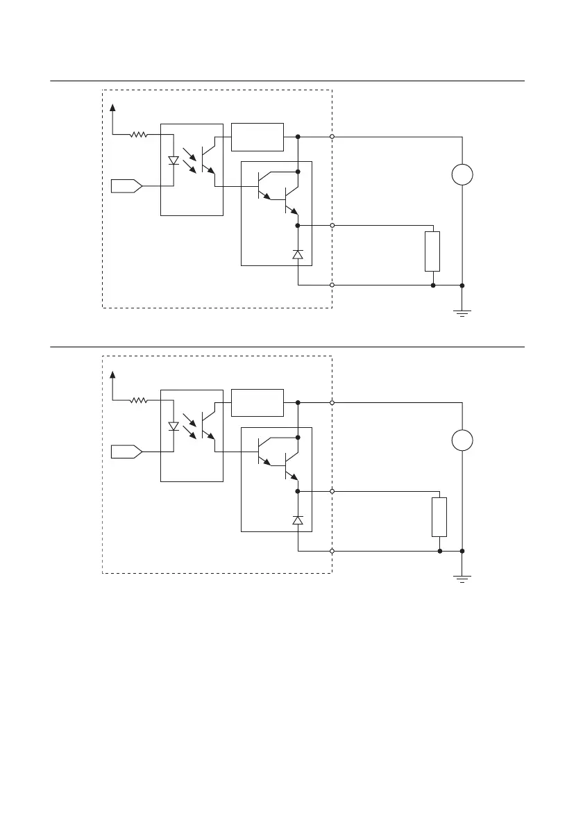
Figure 4-7. NI 6516 Output Signal Connection Example
Figure 4-8. NI 6518 Output Signal Connection Example
Distributing Current (NI 6516/6518 Only)
In applications that drive many high-current loads, a large amount of current must be returned
on the VCC pins. When connecting the NI 6516/6518 to multiple loads, physically connect to
all VCC pins on the device, as shown in Figure 4-9 and Figure 4-10. Connecting to all VCC pins
distributes the current evenly among the VCC pins and lowers the amount of current driven on
any single cable wire and on the accessory terminals.
Voltage
Regulator
COM (GND)
P<0..3>.<0..7>
+
–
DC
LOAD
+5 V ~ +30 V
Output
Photocoupler
+3.3 V
VCC
NI 6516
Darlington
Driver
Voltage
Regulator
COM (GND)
P<2..3>.<0..7>
+
–
LOAD
+5 V
~ +30 V
DC
Output
Photocoupler
+3.3 V
VCC
NI 6518
Darlington
Driver

 Loading...


