3-4 | ni.com
Chapter 3 I/O Information
VGA
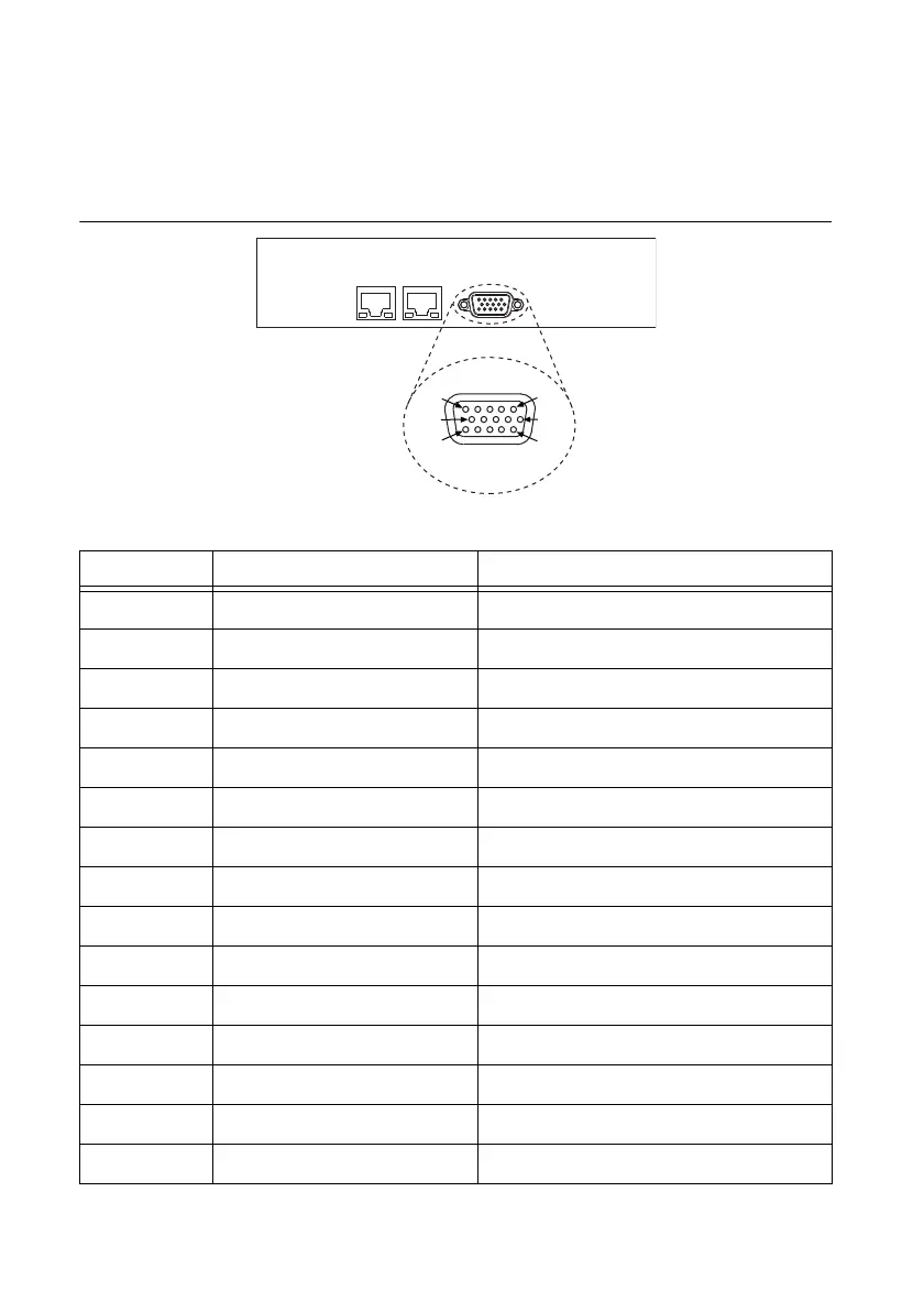
Figure 3-4 shows the location and pinouts for the VGA connector on the RMC-8357. Table 3-5
lists and describes the VGA connector signals.
Figure 3-4. VGA Connector Location and Pinout
Table 3-5. VGA Connector Signals
Pin Signal Name Signal Description
1 R Red
2 G Green
3 B Blue
4 NC Not Connected
5 GND Ground
6 GND Ground
7 GND Ground
8 GND Ground
9 +5V 5 V
10 GND Ground
11 NC Not Connected
12 SD Serial Data
13 HSync Horizontal Sync
14 VSync Ve r t i c a l S y n c
15 SC Serial Clock
VGA
15
10
5
11
6
1

 Loading...