© National Instruments | 3-5
RMC-8357 User Manual
Ethernet
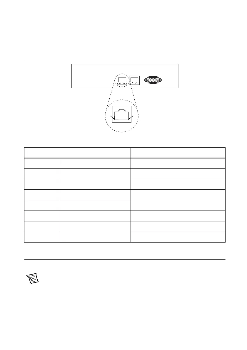
Figure 3-5 shows the location and pinouts for the Ethernet connectors on the RMC-8357.
Table 3-6 lists and describes the Ethernet connector signals.
Figure 3-5. Ethernet Connector Location and Pinout
MXI-Express Connectors
Refer to your MXI-Express hardware user manual for connector information.
Note The RMC-8357 BIOS supports only 188 PCI buses by default. For large
multichassis systems requiring more than 188 PCI buses, use the NI MXI-Express
BIOS Compatibility Software to work around this limitation on Windows. To access
the NI MXI-Express BIOS Compatibility Software, search for MXI-Express BIOS
Compatibility Software at
ni.com/drivers.
Table 3-6. Ethernet Connector Signals
Pin Signal Name Signal Description
1 D0P Differential Pair 0+
2 D0N Differential Pair 0-
3 D1P Differential Pair 1+
4 D2P Differential Pair 2+
5 D2N Differential Pair 2-
6 D1N Differential Pair 1-
7 D3P Differential Pair 3+
8 D3N Differential Pair 3-
Ethernet
1
8

 Loading...