English – 13
06. The force adjustment is an important safety factor and must be done with the utmost care by qualied technicians. Important! - Adjust
the force sufciently to enable the gate to move as intended; higher force values to those necessary for moving the gate can cause injury
to animals and persons or damage to property if the gate collides with an obstacle
07. Before commissioning the automation, adequately inform the owner in writing regarding the attendant residual risks
7
PROGRAMMING
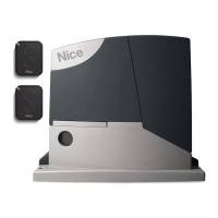
7.1 - Programming buttons
A number of programmable functions are available on the ROAD control unit; they can be adjusted using 4 buttons on the control unit and are
displayed through 4 LEDs: L1, L2, L3, L4(R).
The default settings should satisfy most requirements, but can be modied at any time using the appropriate programming procedure; see
Paragraph 7.6.
Buttons Function
L4(R)
L1L2L3
Close
Open
Stop/Set
Flash
Photo
Photo Test
Stop
GND
SbS
24 V
Aerial
Open s
The “OPEN” button enables the user to control opening of the gate or move the program-
ming point upwards.
Stop /
Set
The “STOP” button can be used to stop the manoeuvre; if pressed for more than 3 sec-
onds, it allows for entering the programming mode, as described below.
Close
t
The “CLOSE” button enables the user to close the gate or move the programming point
downwards.
Radio
The “RADIO” button allows for memorising and deleting the transmitters to be used with
ROAD.
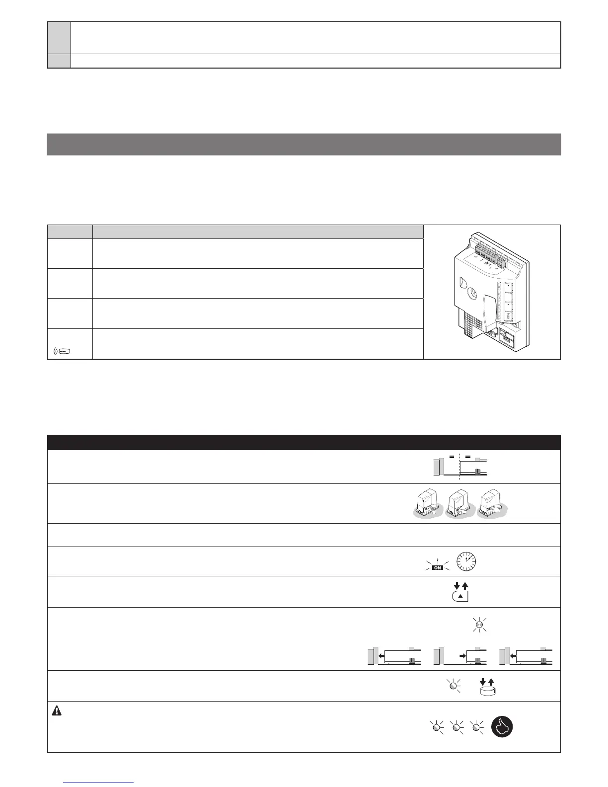
7.2 - QUICK SET-UP
The “Quick set-up” function allows for speeding up the motor’s commissioning. It only works with an empty memory.
This procedure allows for detecting and memorising the STOP input conguration, the presence or absence of the connection in “Phototest”
mode of the PHOTO input, the opening and closing positions and the transmitter (if present) memorised in Mode 2 with the Step-by-Step control.
Memorisation procedure
Table 6 - Procedure for Quick set-up
01. Move the gate leaf to the halfway position of its path
02. Lock the gearmotor
03. Set the direction in relation to the gearmotor’s position with respect to the
gate leaf
see Paragraph 5.1
04. Power the control unit through the mains and wait 10 seconds
10 s
05.
Press and release s
06. Device recognition phase:
LEDs L2 and L3 ash rapidly for the entire duration of the recognition phase
and the gate performs the closing, opening and closing manoeuvres
L2 and L3
06. LED L4(R) ashes once every second: press and release the button of the
transmitter to be memorised
L4(R) ...
If the memorisation procedure was successful, LED L4(R) on the control unit
will ash 3 times.
Repeat the procedure for each transmitter to be memorised.
The memorisation phase terminates if no further transmitters are memorised
for 10 seconds.
L4(R)
 Loading...