18 – English
8
FURTHER INFORMATION
8.1 - Adding or removing devices
It is possible to add or remove devices at any time; in particular, various types of devices can be connected to the STOP input, as described in
the following paragraphs; for the relevant procedure see Paragraph 7.3 (“Recognition of the gate opening and closing positions”).
STOP input
STOP is the input that causes the immediate interruption of the manoeuvre, followed by a brief inversion. Devices with output featuring normal-
ly open Normally Open (NO) contact, Normally Closed (NC) contact, as well as devices with 8.2 kΩ xed resistance output, such as sensitive
edges, can be connected to this input.
The control unit recognises the type of device connected to the STOP input during the recognition phase (Paragraph 7.3 “Recognition of
the gate opening and closing positions”); subsequently, a STOP command is triggered whenever the device detects any difference from the
recognised setting.
Multiple devices, even of different types, can be connected to the STOP input if suitable arrangements are made:
- Multiple NO devices can be connected to each other in parallel without any quantity limit.
- Multiple NC devices can be connected to each other in series without any quantity limit.
- Multiple devices with 8.2 kΩ xed resistor can be “cascade” connected with a single 8.2 kΩ terminating resistor
- NO and NC combinations can be made by placing the 2 contacts in parallel, taking care to place an 8.2 kΩ resistor in series to the NC con-
tact (this allows for combining 3 devices: NO, NC and 8.2 kΩ).
If the STOP input is used to connect devices with safety functions, only the devices with 8.2 kΩ xed resistor guarantee Category 3 safety
against faults, in accordance with the EN 13849-1 standard.
Photocells
The control unit features a “Phototest” function which increases the reliability of the safety devices, enabling it to be classied in Category 2
in accordance with the EN 13849-1 standard regarding the combination of the control unit and safety photocells.
Each time a manoeuvre is started, all safety devices involved are checked and only in the case of positive results will the manoeuvre be
started.
Should the test fail (photocell blinded by the sun, cables short-circuited, etc.), the fault is identied and the manoeuvre is disabled.
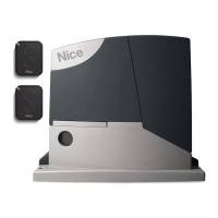
To add a pair of photocells, connected them as described below.
• Connection without “Phototest” function:
Power the receivers directly from the control unit’s device output (ter-
minals 1 - 4).
NO
FLASH
2
Flash
87 65 43 21
Photo Test
Photo
GND
Stop
SbS
L1L2L3
L4(R)
24 V
Aerial
TX
112345 2
RX
OpenStop/SetClose
OFF
L4(R)
L1L2L3
Close
Open
Stop/Set
Flash
Photo
Photo Test
Stop
GND
Sb
S
24 V
Aerial
NC
8k2
NO
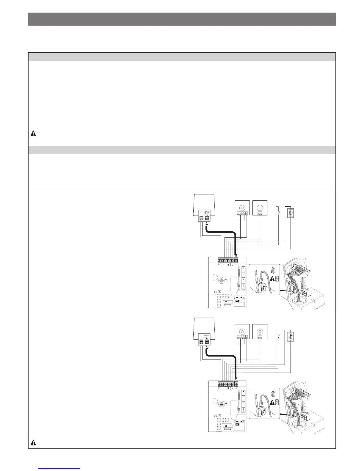
• Connection with “Phototest” function:
The photocell transmitters are not powered directly from the devic-
es output, but from the “Phototest” output between terminals 6 - 4.
The maximum admissible current on the “Phototest” output is 100
mA.
NO
NC
8k2
NO
 Loading...