20 – English
9
DIAGNOSTICS
The control unit emits special signals showing the operating status or any malfunction.
The OK LED can ash red if an anomaly is detected during normal operation; in particular, it will ash several times followed by a 1-second pause
to signal the specic error/anomaly
9.1 - Warning light signals and courtesy light
Table 17 - Warning light signals and courtesy light
Signal Cause Solution
2 ashes
1-sec pause
2 ashes
Intervention of a photocell At the start of the manoeuvre, one or more photocells prevent movement; check
whether there are any obstacles.
This is normal when there is an obstacle hampering the closing movement.
3 ashes
1-sec pause
3 ashes
Intervention of the
“Motor Force” limiter
During the movement, the gate experienced excessive friction; identify the cause.
4 ashes
1-sec pause
4 ashes
Triggering of the STOP input
At the start of the manoeuvre or during the movement, the STOP input intervened;
identify the cause.
5 ashes
1-sec pause
5 ashes
Internal parameter memorisation
error
Wait at least 30 seconds during which the control unit will attempt to restore the
function. If the condition persists, delete the memory and rerun the memorisation
procedure.
6 ashes
1-sec pause
6 ashes
Maximum number of manoeuvres
per hour exceeded
Wait a few minutes until the manoeuvre limiting device drops below the maximum
limit.
7 ashes
1-sec pause
7 ashes
Error in the internal electric circuits Disconnect all the power circuits for a few seconds and then try giving a command
again; if the condition persists it means there is a serious fault on the electronic board
or the motor cabling: perform the necessary checks and replace components, if nec-
essary.
8.4 - Full deletion of the memory
When full deletion of the memory is required, to restore the default settings, perform the following procedure with the motor stationary:
Table 16 - Procedure for fully deleting the memory
01.
Press and hold buttons s and t simultaneously for 3 seconds.
3 s
02. When all the LEDs light up simultaneously, release the buttons.
03. LEDs L1, L2 and L3 will start ashing at the end of the procedure.
After full deletion, the limit switch recognition procedure can be restarted by running the “Quick Set-up” procedure (Paragraph 7.2).
Important - This procedure does not cancel the transmitters.
8.5 - Special functions
“Always open” function
This function is a control unit feature that enables the user to command an opening manoeuvre when the “Step-by-Step” command lasts
longer than 3 seconds. This is useful, for example, for connecting a timer contact to the “Step-by-Step” input in order to keep the gate open
during a specic time bracket.
This feature is valid regardless of the “Step-by-Step” input programming (see the “Step-by-Step Function” parameter - Table 11).
“Move anyway” function
In the event that one of the safety devices is not functioning properly or is out of order, it is still possible to command and move the gate in
“Man present” mode. For further details, refer to the “USER GUIDE” pull-out insert (nal part of the manual)
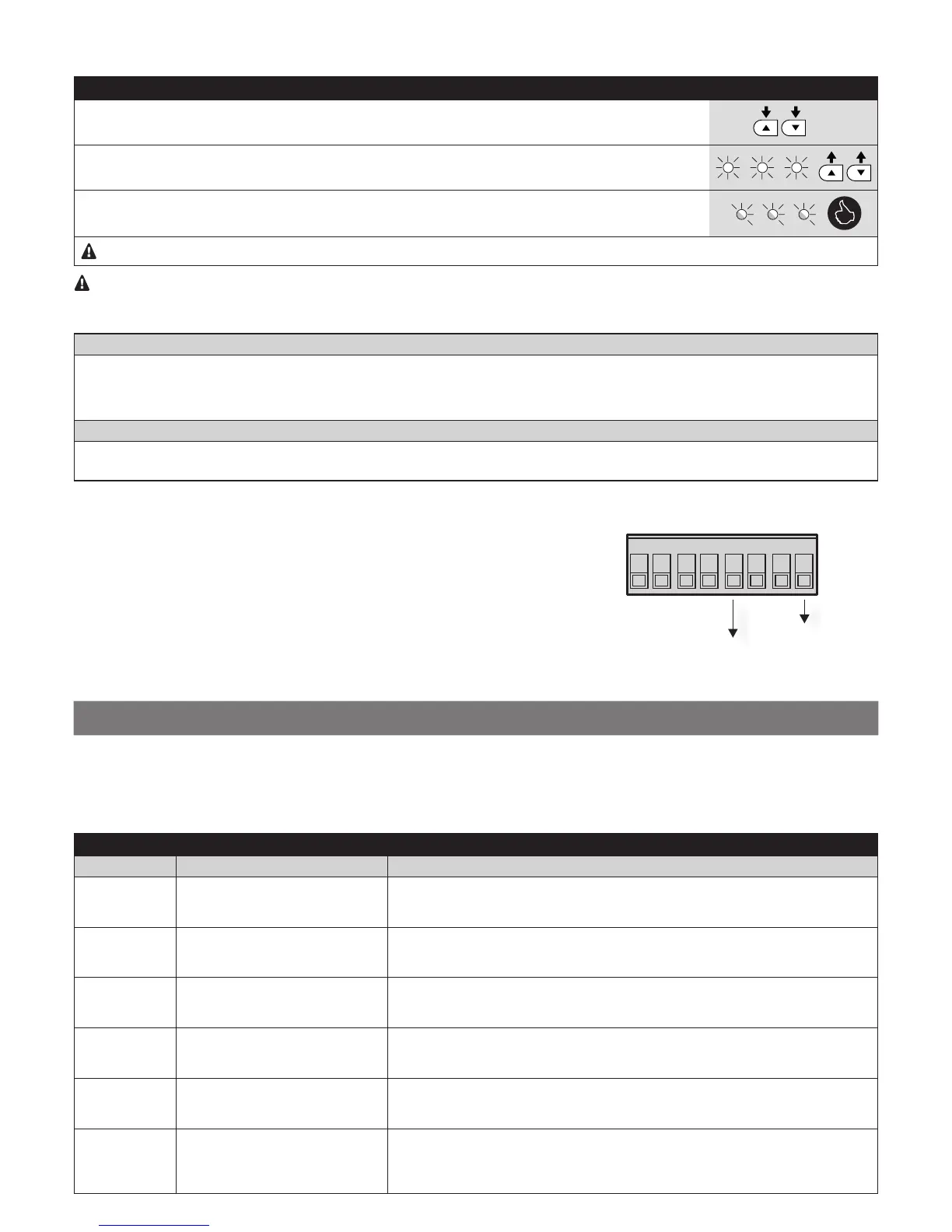
8.6 - Power for external devices
To power external devices (proximity reader for transponder cards or the backlight
of a key selector) it is possible to connect the device to the product’s control unit as
shown in the adjacent gure.
The power supply voltage is 24 VDC –30% to +50% with a maximum available current
of 100 mA.
87 65 43 21
0 (-)

 Loading...