22 – English
12
MAINTENANCE
To ensure constant safety levels a long service life, the system must be serviced regularly: at least every 6 months or after maximum 10,000
movements since the last service.
WARNING! – Maintenance operations must be performed in strict compliance with the safety precautions provided in this man-
ual and according to applicable legislation and standards.
01. Disconnect the power supply to the gearmotor and check the state of deterioration of all the automation’s constituent materials:
pay special attention to erosion and oxidation of structural components. Replace any parts that are not to standard
02. Check the state of wear of moving parts: pinion, rack and all parts of the gate leaf; replace any worn components if necessary
03. Power the gearmotor and run all the tests and checks indicated in Paragraph 6.1 - Testing
11
PRODUCT DISPOSAL
This product constitutes an integral part of the automation and, therefore, must be disposed of together with it.
Similarly to the installation phase, once the product reaches the end of its useful life, the disassembly and scrapping operations must be per-
formed by qualied personnel.
This product is made of various types of materials, some of which can be recycled while others must be scrapped. Seek information on the
recycling and disposal systems envisaged by local regulations in your area for this product category.
WARNING! - Some parts of the product may contain polluting or hazardous substances which, if released into the environment,
constitute serious environmental and health risks.
As indicated by the adjacent symbol, the product may not be disposed of together with domestic waste. Sort the materials for
disposal, according to the methods envisaged by current legislation in your area, or return the product to the retailer when pur-
chasing an equivalent product.
WARNING! - Local regulations may envisage the application of heavy nes in the event of improper disposal of
this product.
10
TROUBLESHOOTING
Table 20 contains useful instructions to help you solve malfunctions or errors that may occur during the installation stage or in case of fault.
Table 20 - Troubleshooting
Problem Solution
The radio transmitter does not control the gate
and the LED on the transmitter does not light
up
Check to see if the transmitter batteries are exhausted and replace them if necessary.
The radio transmitter does not control the gate
and the LED on the transmitter lights up
- Check whether the transmitter has been memorised correctly in the radio receiver.
- Check whether the transmitter emits the radio signal correctly by means of this practical
test: push a button and place the LED on the antenna of a normal radio
(preferably a cheap
one) that is switched on and tuned to 108.5 Mhz FM or as close as possible; a slight crackling
sound should be heard.
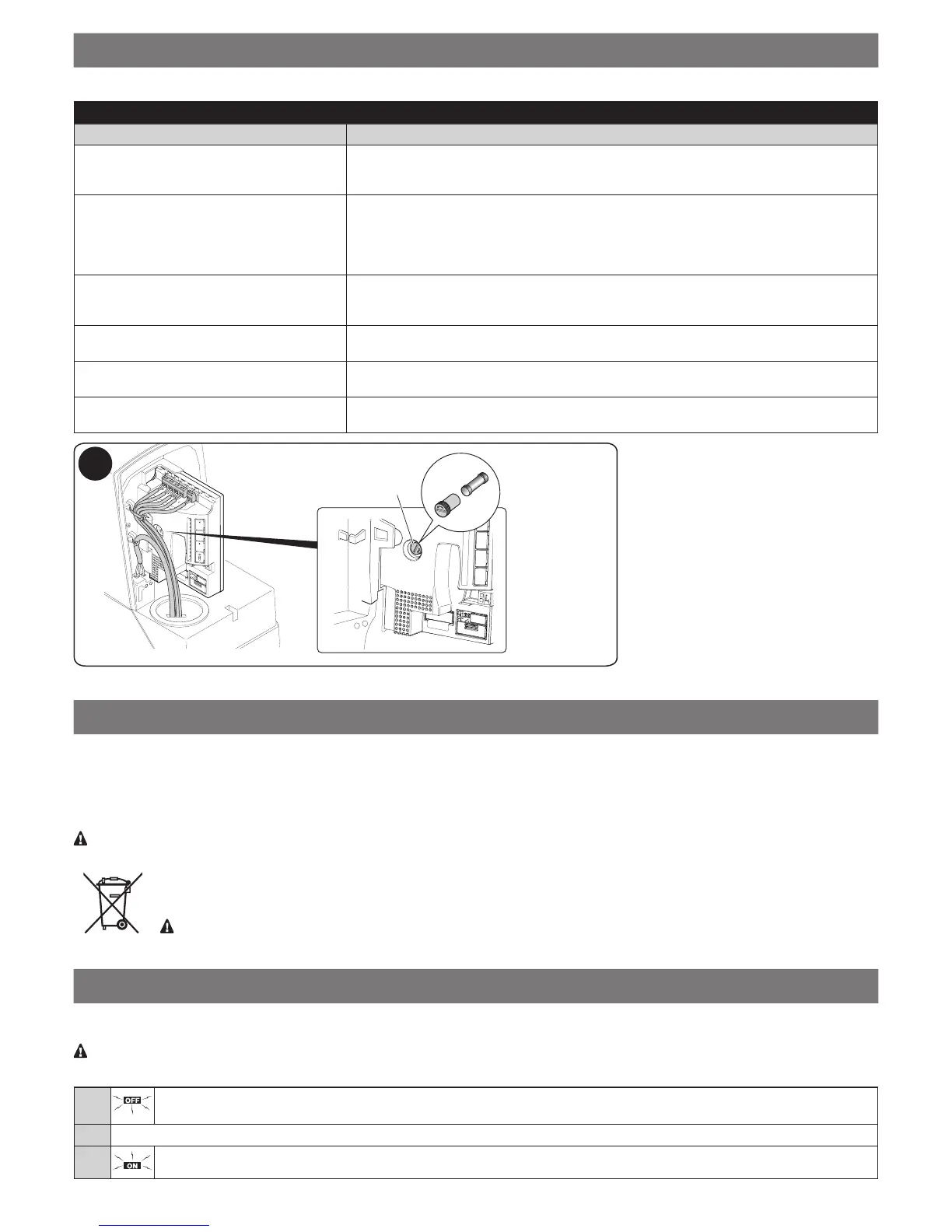
No manoeuvre starts and the OK LED fails to
ash
Check whether the gearmotor is powered at 230 V mains voltage. Check that fuse F2 has
not blown; if it has, identify the reason for the fault then replace it with one of the same current
rating and characteristics (Fig. 11).
No manoeuvre starts and the warning light is
off
Check that the command is actually received. If the command reaches the Step-by-Step
input, the OK LED ashes twice indicating that the command has been received.
The manoeuvre does not start and the courte-
sy light ashes a few times
Count the number of ashes and check them against Table 19.
The manoeuvre starts but it is immediately fol-
lowed by a brief reverse run
The selected force value may be too low to move the gate: check whether there are any ob-
stacles and, if necessary, select a greater force or check whether the limit switch is blocked.
L4(R)
L1L2L3
Close
Open
Stop/Set
Flash
Photo
Photo Test
Stop
GND
SbS
24 V
Aerial
F2
F1
11

 Loading...