MOTOR
4
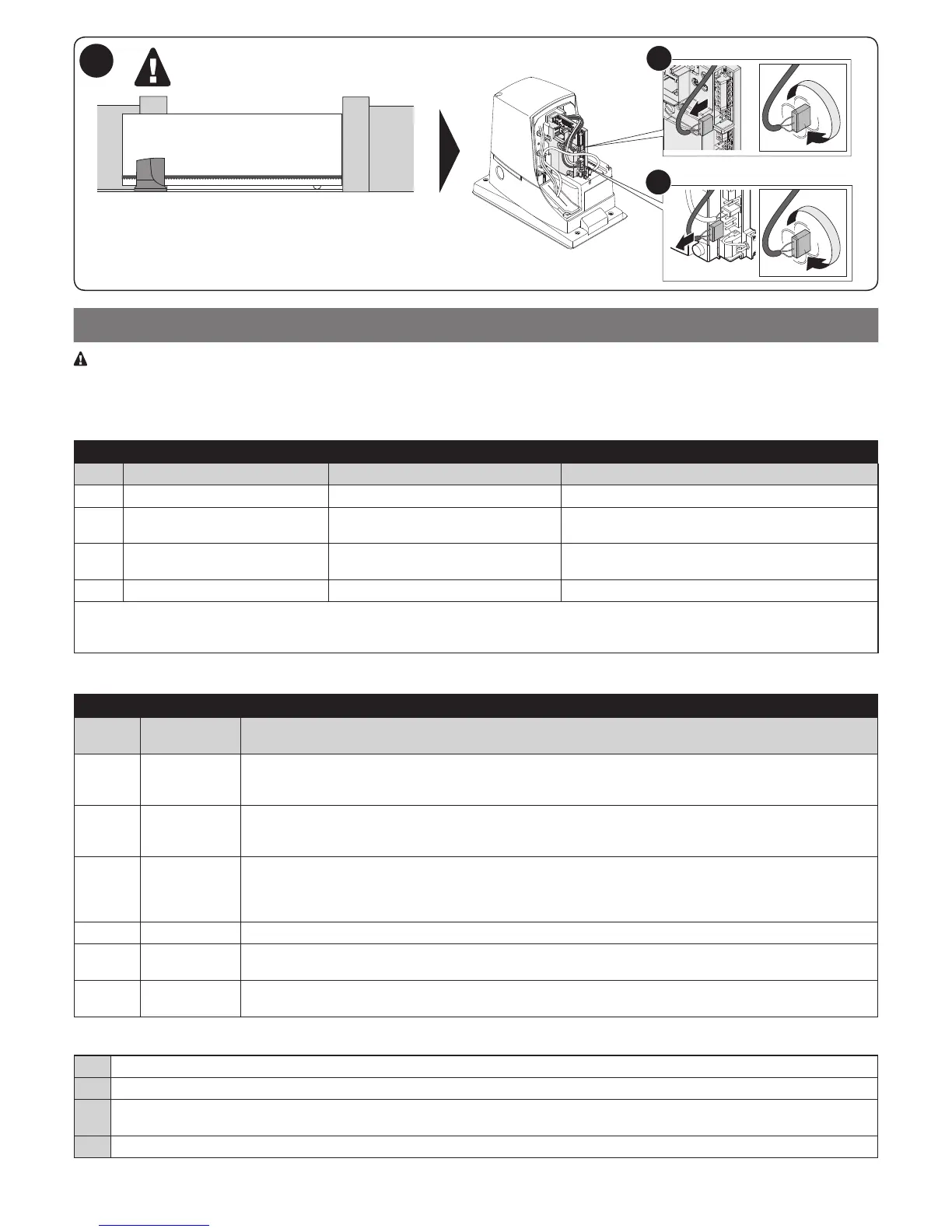
ELECTRICAL CONNECTIONS
CAUTION! - All electrical connections must be carried out with the system disconnected from the mains. Incorrect connections
can cause damages to the equipment and injuries to people.
Fig. 2 shows the hookup of a typical installation; g. 7 shows the connections to be made on the control unit.
4.1 - Types of electrical cables
Table 3 - Types of electrical cable (see g. 2)
Connection Type of cable Maximum length
A POWER 3 x 1.5 mm
2
30 m *
B
C
FLASHER WITH AERIAL 1 cable: 2 x 1.5 mm
2
1 shielded RG58 cable
10 m
10 m (< 5 m recommended)
D PHOTOCELLS 1 cable: 2 x 0.25 mm
2
(TX)
1 cable: 4 x 0.25 mm
2
(RX)
30 m
30 m
E - F KEY SWITCH 1 cable: 2 x 0.5 mm
2 **
20 m
* A power supply cable longer than 30 m may be used provided it has a larger gauge, e.g. 3 x 2.5 mm
2
, and that a safety grounding system
is provided near the automation unit.
** The two 2 x 0.5 mm
2
cables can be replaced by a single 4 x 0.5 mm
2
cable.
4.2 - Electrical cable connections: g. 7
Table 4 - Description of electrical connections
Termi-
nals
Function Description
9 - 10 Stop - input for devices that lock or stop the current operation; with appropriate precautions, “Normally Closed” or
“Normally Open” contacts or constant resistance devices can be connected to the input.
Other information on STOP can be found in paragraph 8.1.1 - STOP input
9 - 11 Photo - input for safety devices which when tripped reverse the gate's direction of movement: NC (Normally Closed)
contacts may be used
- for further details, refer to par. 8.1.2 Photocells.
8 - 12 Phototest Every time a manoeuvre is started, the operation of the photocells is checked; the manoeuvre starts if the test
is positive. This is possible using a particular type of connections: the transmitters of the “TX” photocells are
powered separately than the “RX” receivers.
For further details, see paragraph 8.1.2 Photocells.
9 - 13 Step-by-step input for devices which control movement. NO (Normally Open) contacts can be connected
4 - 5 Flashing light - asher output (auto-intermittent)
- when active, the output supplies 230 V~ (120V~ on V1 / motor version)
1 - 2 Aerial - radio receiver aerial input
- aerial integrated into asher; an external aerial can be used if desired
To make the electrical hookup, proceed as described below with reference to g. 7:
01. Open the cover: undo the screw and raise the cover
02. Run the power cable through the hole (leave 20/30 cm of free cable) and connect it to its terminal clamp
03. Run the cables of the equipment to be installed or already present through the provided hole (leave 20/30 cm of free cable) and connect
them to their terminal clamps (see g. 14)
04. Perform the desired programming: chapter 7
 Loading...