English – 19
8
FURTHER DETAILS
8.1 - Adding or removing devices
Automation devices can be added or removed at any time; in particular at the STOP input, various types of devices can be connected as
described in the following paragraphs;
WARNING! - at the end of the modications made to the conguration of the alt input and of the
photocell input it is necessary to repeat the device learning procedure as described in paragraph 5.2.
8.1.1 STOP input
Input that stops movement immediately, followed by a brief reverse of the manoeuvre.
Devices with NO (normally open), NC (normally closed) contact output or with output with 8.2kΩ constant resistance, for instance sensitive
edges, can be connected to this input. The control unit recognizes the type of device connected to the STOP input while acquiring the devices
(paragraph 7.3 Learning the devices).
In the presence of any change from the initial recognition, the automation stops and reverses its direction briey.
With appropriate precautions, it is possible to connect more than one device, even of different type, to the STOP input:
- Numerous NO devices can be connected in parallel between themselves without any limit in quantity.
- Numerous NC devices can be connected in series between themselves without any limit in quantity.
- Numerous 8.2kΩ constant resistance devices can be connected “in cascade” with just one 8.2kΩ terminating resistor
- The combination of NO and NC is possible putting the 2 contacts in parallel with the warning of putting an 8.2kΩ resistor in series with the NC
contact (this makes the combination of 3 devices also possible: NO, NC and 8.2kΩ ).
If the STOP input is used to connect devices with safety functions, only the devices with 8.2kΩ constant resistance output guarantee category
III safety against faults in compliance with the EN 13849-1 standard.
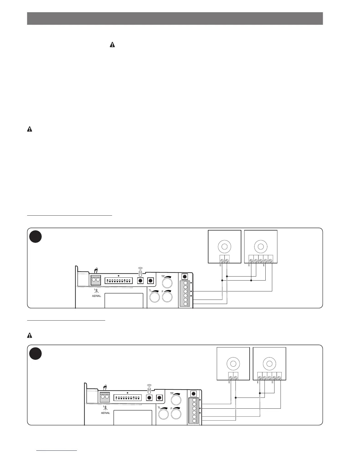
8.1.2 Photocells
To add a pair of photocells, proceed as follows:
01. Power up the receivers (RX) via terminals 8 - 9 (see drawing 7)
On the other hand, the connection method of the transmitters depends on whether we want photocells to operate with the phototest mode
active.
Phototest is a function in the control unit that increases the reliability of the safety devices, allowing reaching “category II” in compliance with the
EN 13489-1 standard, with regard to the control unit and safety photocell assembly.
When a manoeuvre is activated, the involved safety devices are checked and the manoeuvre starts only if everything is OK.
If the test is negative (photocell blinded by the sun, wires short circuited, etc.), the fault is detected and the manoeuvre is not carried out.
To add a pair of photocells, connect them as follows.
Connection without “Phototest” function:
Power the transmitters and receivers directly from the service output of the control unit (terminals 8 and 9).
 Loading...