- A ・ -
Q0340グラフィック用ロゴ
060411デザイン部伊藤
VBA14001-R.3694.A
#695×2
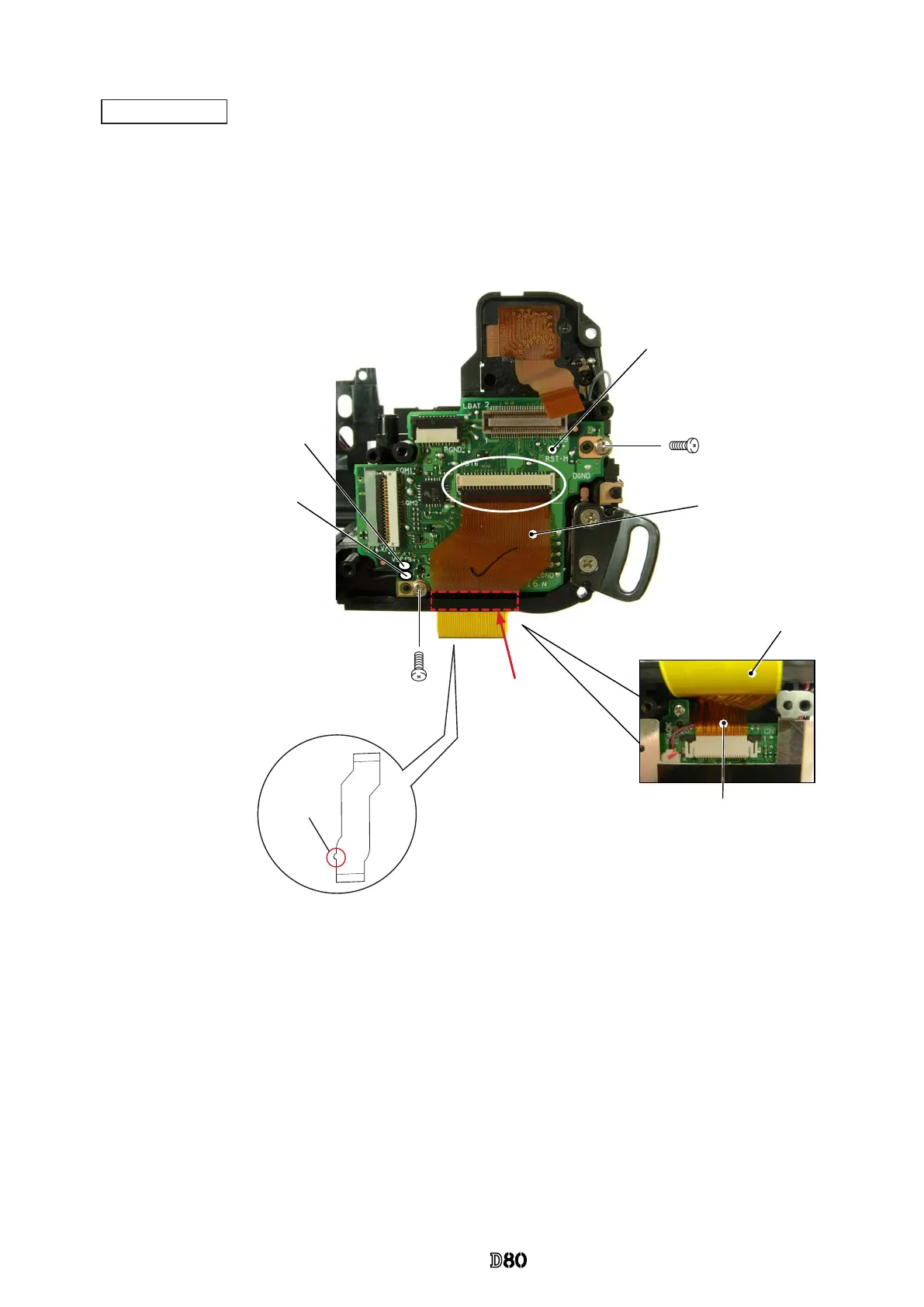
Main PCB unit (#B1001)
・
Mount the main PCB unit (#B1001).
・
Tighten two screws (#695).
・
Solder the two wires of the electronic buzzer unit.
・
Connect the main PCB-FPC (#B1001) to the connector of the DC/DC PCB.
・
Connect the connection-FPC (#1023) to the connector, and pass it through the groove.
Main PCB unit FPC (#B1001)
Connection-FPC (#1023)
Black wire:
Electronic buzzer unit
Black wire:
Electronic buzzer unit
Groove
Connection-FPC (#1023)
Be careful of the
direction of the
convex portion.
Connection-FPC (#1023)
Main
PCB unit

 Loading...