- A ・ -
Q0340グラフィック用ロゴ
060411デザイン部伊藤
VBA14001-R.3694.A
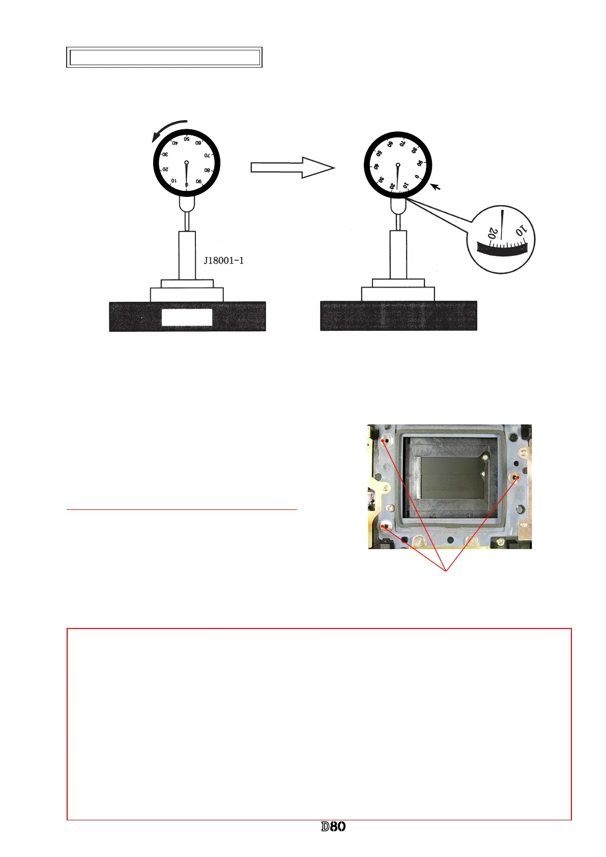
Measuring point
0
0
0
0
0
0
0
0
0
0
0
0
Inspection and Adjustment of Body back
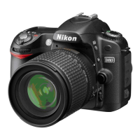
* "0" positioning of the dial gauge
0" position of D80
Surface plate
①
Put the tool (J18001-1) on the surface plate, and set the dial gauge to "0".
②
Turn the index ring in the direction of the arrow, and set to the scale "17
"
from "0" that was set in
①
. (This
is "0"-position of D80.)
③
Measure the body back based on "0" reference position of the index ring.
・
Measure three parts from the bayonet face to the CCD-
PCB attaching face.
Standard:48.50±0.015mm/ Parallelism: within 0.015mm
・
In case it is out of standard, make an adjustment
by loosening screws that attach the front and rear bodies,
or
by putting the washer(s) on the contact surface between
the front body and rear body.
Note: For some bodies, washer(s) are already put on the attaching face of the CCD-bracket.
There are two cases as follows.
1. Purpose
:
To adjust the height of the camera body
There are indications by color marker (washer thickness) on the camera body side of the CCD-PCB attach-
ing face.
{Blue =0.02mm (#63A), Red
=
0.01mm (#63B), Green
=
0.06mm (#63C)}
*
By adding the measured value to the thickness of washers, check if it is within the standard (48.50±0.015mm).
2. Purpose
:
To adjust the height of the CCD bracket
There are indications by red marker of the CCD-bracket attaching face
{Red circle
=
0.1 mm (#63B)} (Washers are equally put on the three locations.)
*
When the CCD PCB is replaced, remove the washers.
 Loading...