Installation
A1-2
E 2000 Nordson Corporation
All rights reserved
41-3000V
Issued 5/00
A3EN-04-[3V-A-AAXP]-12
Carefully select the location for the unit and its associated guns and
hoses. Make sure that the location meets the following requirements:
S There is enough room to open the tank lid, open the electrical
enclosure, remove the filter assembly, remove the pump enclosure,
and make electrical connections for the hoses. For unit dimensions
and recommended clearances, refer to Dimensions in the Description
section of this manual.
S An operator can reach all controls.
S Maintenance personnel have room to service and repair the unit.
S Installers can route the hoses without bending them. The minimum
bend radius for hoses is shown in Figure A 1-8.
S The mounting surface can support the weight of the unit when the unit
is filled with adhesive. Refer to Specifications in the Description
section of this manual.
S The mounting surface is level.
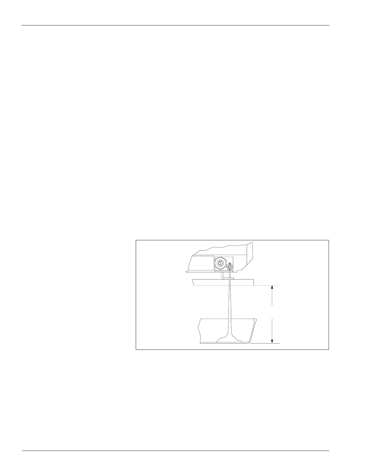
S The mounting surface is raised at least 152 mm (6 in.) for draining
adhesive. See Figure A 1-1.
S The drain valve projects over the edge of the mounting surface.
4130685A
152 mm
(6.0 in.)
Fig. A 1 -1 Required Clearance for Draining and Filter Flushing
oca
o
equ
e
e
 Loading...


