5 - 5
5 DriveProgramming User Variables
DriveProgramming User’s Manual (I622-E1)
5-2 Input/Output Terminal Variables
5
5-2 Input/Output Terminal Variables
This section describes the variables provided for using the following inverter terminals for the
DriveProgramming function: Input terminals, output terminals, relay outputs, analog input terminals,
and analog output terminals. Use these variables as the interface between the inverter's peripheral
devices and the DriveProgramming function.
You can use the inverter's input terminals as the input terminal variables X(00) to X(10) for the Drive-
Programming function by setting these input terminals to the general-purpose input MI1 to MI11.
When Xw variables are used, the input terminal variables X(00) to X(10) can be used as word access
data.
• The status of the input terminals 1 to 9, A and B is captured and set as bit-size variables. This vari-
able is read-only.
• When the input terminals 1 to 9, A and B Selection (CA-01 to CA-11) are set to 86 to 96 (MI1 to MI11:
General-purpose input), the status of the input terminals 1 to 9, A and B is captured and set as the
input terminal variables X(00) to X(10) of the DriveProgramming.
Numbers are given to the input terminal variables X(00) to X(10) according to the numerical order of
the set general-purpose inputs MI1 to MI11, not the terminal numbers 1 to 9, A and B.
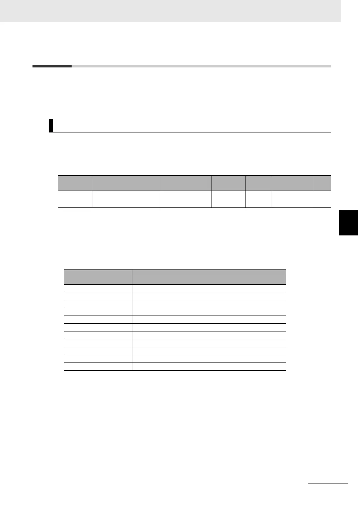
Input Terminal Variables X(00) to X(10)
Function
variable
Description Data range
Default
data
Unit Data size R/W
X(00) to
X(10)
Input terminal variable
(bit access)
0: OFF
1: ON
0 − bit R
Function variable Input Terminal (CA-01 to CA-11)
X(00) 86: MI1
X(01) 87: MI2
X(02) 88: MI3
X(03) 89: MI4
X(04) 90: MI5
X(05) 91: MI6
X(06) 92: MI7
X(07) 93: Ml8
X(08) 94: Ml9
X(09) 95: Ml10
X(10) 95: Ml11
 Loading...


